03 Ranger swap (and questions!)
#1
 12-31-2014


Join Date: Aug 2014
Location: Portland, OR
Posts: 93
Likes: 0
Received 0 Likes
on
0 Posts
03 Ranger swap (and questions!)
I'm looking at 2 different Explorers this weekend for my 2003 Ranger XLT (formerly 4WD). I no longer have 4WD and am swapping with all 2WD components from an Explorer, or building as such. The Explorers at the tow yard are a 99 5.0 AWD, and a 97 5.0 2WD. I really would like the 97 due to not having to redo a tranny as a 2WD, or source out a new one.. But also, it only has 103k on it! I'm aware of the PATS, return fuel line, and VSS differences (which really makes it easier it seems) but I haven't seen a definitive answer to if I will run into issues with the mounts from a 97 Explorer to my 03 XLT... Can anyone confirm this? I haven't seen it mentioned as a problem in tech articles or anything, but I want to make sure. I saw a similar post a page back about swapping a 97 into an 03 Ranger, but mounts were never mentioned. I'm hoping this is because the engine will mount right up.
I'm also going off of the assumption the the 2WD tranny will mount to my frame... Not sure about this, but if not, I can always build a mount.
Any input on these issues would be greatly appreciated as I'm looking to buy one this weekend. Then I should be turning this into a build thread.
Thanks
I'm also going off of the assumption the the 2WD tranny will mount to my frame... Not sure about this, but if not, I can always build a mount.
Any input on these issues would be greatly appreciated as I'm looking to buy one this weekend. Then I should be turning this into a build thread.
Thanks
Last edited by JB5587; 12-31-2014 at 12:54 AM.
#2
12-31-2014
Join Date: Aug 2014
Location: Portland, OR
Posts: 93
Likes: 0
Received 0 Likes
on
0 Posts
Went and looked at the 97. It starts right up and sounds good. It was owned by an old lady. Fluids look great and there doesn't seem to be anything wrong. One of the only 2WD 5.0's I've seen anywhere in Oregon as well which is awesome. Some oil leaking from around the oil pan, but it doesn't appear to be anything more than a gasket (hopefully). Picking it up on Saturday. Hopefully it fits and I don't run into any problems.

#4
12-31-2014
Join Date: Aug 2014
Location: Portland, OR
Posts: 93
Likes: 0
Received 0 Likes
on
0 Posts
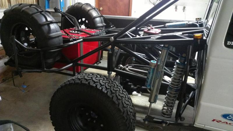
That's what I've gathered so far, but I was just trying to make sure for pre 98 vehicles as well. I honestly never knew torsion bars were used on anything pre 98, but I looked under the Explorer just to check. Pretty cool.
#5
12-31-2014
Join Date: Aug 2014
Location: Portland, OR
Posts: 93
Likes: 0
Received 0 Likes
on
0 Posts

#9
01-03-2015
Join Date: Aug 2014
Location: Portland, OR
Posts: 93
Likes: 0
Received 0 Likes
on
0 Posts
Yeah a little. I'm trying to figure out (after 3 days of relentless googling) what cam and rockers to go with. I want to do a cam, roller rockers, and springs. I've read a lot that the GT40 springs (not GT40p) can handle the Mustang 303 cams fine, so I might just do the cam (probably an E-303) right now and upgrade the rockers and stuff later. Also replacing the shitty 96-98 tube headers with the 99+ cast ones. Other than that, just plugs, wires, water pump, good fluids, etc... Just doing the stuff now that I'll want in the near future. I will definitely upgrade a lot as time goes on.
#10
01-03-2015
Yeah a little. I'm trying to figure out (after 3 days of relentless googling) what cam and rockers to go with. I want to do a cam, roller rockers, and springs. I've read a lot that the GT40 springs (not GT40p) can handle the Mustang 303 cams fine, so I might just do the cam (probably an E-303) right now and upgrade the rockers and stuff later. Also replacing the shitty 96-98 tube headers with the 99+ cast ones. Other than that, just plugs, wires, water pump, good fluids, etc... Just doing the stuff now that I'll want in the near future. I will definitely upgrade a lot as time goes on.
#11
01-03-2015
Join Date: Aug 2014
Location: Portland, OR
Posts: 93
Likes: 0
Received 0 Likes
on
0 Posts
#12
01-03-2015
Yep. Mine is out of a 98.
Since you mentioned upgrading plugs and wires, this (clicky) may be something you want to consider. I just picked this up myself a few days ago. Hasn't come in yet though. I know the Screamin Demons used to be a really popular upgrade for Rangers, and they get good reviews from the Explorer guys as well.
Since you mentioned upgrading plugs and wires, this (clicky) may be something you want to consider. I just picked this up myself a few days ago. Hasn't come in yet though. I know the Screamin Demons used to be a really popular upgrade for Rangers, and they get good reviews from the Explorer guys as well.
#13
01-04-2015
Join Date: Jan 2014
Location: Tampa, Florida
Posts: 94
Likes: 0
Received 0 Likes
on
0 Posts
That's a good looking doner Expo you've got there and for the most part, the '96/'97's are the easiest to swap in. No PATS to muck around with. Only the few years of Rangers that share the same PATS and fuel systems as the later Expo's are easier.
Trickiest bit will likely be the A/C wiring.
With an ex-4WD Ranger, things should be pretty easy to get in.
You'll love the Ranger with a 5.0 in the engine bay!
Trickiest bit will likely be the A/C wiring.
With an ex-4WD Ranger, things should be pretty easy to get in.
You'll love the Ranger with a 5.0 in the engine bay!
#14
01-04-2015
Join Date: Aug 2014
Location: Portland, OR
Posts: 93
Likes: 0
Received 0 Likes
on
0 Posts
Yep. Mine is out of a 98.
Since you mentioned upgrading plugs and wires, this (clicky) may be something you want to consider. I just picked this up myself a few days ago. Hasn't come in yet though. I know the Screamin Demons used to be a really popular upgrade for Rangers, and they get good reviews from the Explorer guys as well.
Since you mentioned upgrading plugs and wires, this (clicky) may be something you want to consider. I just picked this up myself a few days ago. Hasn't come in yet though. I know the Screamin Demons used to be a really popular upgrade for Rangers, and they get good reviews from the Explorer guys as well.
That's a good looking doner Expo you've got there and for the most part, the '96/'97's are the easiest to swap in. No PATS to muck around with. Only the few years of Rangers that share the same PATS and fuel systems as the later Expo's are easier.
Trickiest bit will likely be the A/C wiring.
With an ex-4WD Ranger, things should be pretty easy to get in.
You'll love the Ranger with a 5.0 in the engine bay!
Trickiest bit will likely be the A/C wiring.
With an ex-4WD Ranger, things should be pretty easy to get in.
You'll love the Ranger with a 5.0 in the engine bay!

Battery is in the back as well
#15
01-04-2015
Join Date: Jan 2014
Location: Tampa, Florida
Posts: 94
Likes: 0
Received 0 Likes
on
0 Posts
Yea, I think push comes to shove, the later EFI system is probably more efficient but the ease of the '96 wiring more than makes up for it.
For the '96/97 Expo PCM, here are the pin outs for the 42 pin connector between the engine harness and body harness:
One "gotcha" in a simplistic install, the PCM needs to see power from the fuel pump relay at pin #5 -- at a minimum, it only takes about a half dozen wires to get the PCM to light off.
Pin Circuit Color Purpose
1 16 Red Lt Green PCM Power to relay
2 11 Tan/Yellow tachometer data link
3 915 Pink/Lt Blue Data Link Connector pin 10
4 511 Lt Green Brake On/Off switch
5 238 Dk Green/Yellow Power From Fuel Pump Relay (Fuel pump on signal)
6 658 Pink/Lt Green Malfunction Indicator (CEL)
7 679 Gray/Black Speed output from VSS
8 37 Yellow Continuous Power
9 361 Red Fuel Pump relay coil
10 29 Yellow/White Fuel level sender
11 914 Tan/Orange Data Link Connector pin 2
12 224 Tan/White Instrument Cluster
13 676 Pink/Orange VSS and PCM Ground
14 91 Purple/White Canister Vent Solenoid coil
15 926 Lt Blue/Orange Fuel Pump relay coil
16 39 Red/White Engine temp gauge
17 791 Red/Pink Fuel Tank Pressure Transducer (Signal)
18 359 Gray/Red Sensor reference voltage
19 351 Brown/White Fuel Tank Pressure Transducer (Power supply)
20 199 Lt Blue/Yellow Transmission Controls/Clutch Pedal Position Jumper
21 140 Black/Pink reversing lamps at transmission range sensor
22 107 Purple Data Link Connector Pin 13
23
24 329 Pink starter system at transmission range sensor
25 298 Purple/Orange reversing lamps at transmission range sensor
26 253 Dk Green/White oil pressure gauge
27 305 Lt Blue/Pink Message Center pin 5
28 394 Orange/Black Automatic ride control module pin 6
29 784 Lt Blue/Black 4WD Low Range indicator
30 331 Pink/Yellow WOT A/C relay coil
31 32 Red/Lt Blue starter system at transmission range sensor
32
33 463 Red/White Neutral switch for GEM
34 570 Black/White Ground
35
36 34 Lt Blue/Orange PCM Power from relay
37 198 Dk Green/Orange Power to Pin 30 WOT A/C relay
38
39 191 Lt Green/Black Vapor Management Valve coil
40 911 White/Lt Green Transmission Control Indicator in dash (overdrive off lamp)
41
42 570 Black/White Ground
#16
01-04-2015
Join Date: Aug 2014
Location: Portland, OR
Posts: 93
Likes: 0
Received 0 Likes
on
0 Posts
Yea, I think push comes to shove, the later EFI system is probably more efficient but the ease of the '96 wiring more than makes up for it.
For the '96/97 Expo PCM, here are the pin outs for the 42 pin connector between the engine harness and body harness:
One "gotcha" in a simplistic install, the PCM needs to see power from the fuel pump relay at pin #5 -- at a minimum, it only takes about a half dozen wires to get the PCM to light off.
Pin Circuit Color Purpose
1 16 Red Lt Green PCM Power to relay
2 11 Tan/Yellow tachometer data link
3 915 Pink/Lt Blue Data Link Connector pin 10
4 511 Lt Green Brake On/Off switch
5 238 Dk Green/Yellow Power From Fuel Pump Relay (Fuel pump on signal)
6 658 Pink/Lt Green Malfunction Indicator (CEL)
7 679 Gray/Black Speed output from VSS
8 37 Yellow Continuous Power
9 361 Red Fuel Pump relay coil
10 29 Yellow/White Fuel level sender
11 914 Tan/Orange Data Link Connector pin 2
12 224 Tan/White Instrument Cluster
13 676 Pink/Orange VSS and PCM Ground
14 91 Purple/White Canister Vent Solenoid coil
15 926 Lt Blue/Orange Fuel Pump relay coil
16 39 Red/White Engine temp gauge
17 791 Red/Pink Fuel Tank Pressure Transducer (Signal)
18 359 Gray/Red Sensor reference voltage
19 351 Brown/White Fuel Tank Pressure Transducer (Power supply)
20 199 Lt Blue/Yellow Transmission Controls/Clutch Pedal Position Jumper
21 140 Black/Pink reversing lamps at transmission range sensor
22 107 Purple Data Link Connector Pin 13
23
24 329 Pink starter system at transmission range sensor
25 298 Purple/Orange reversing lamps at transmission range sensor
26 253 Dk Green/White oil pressure gauge
27 305 Lt Blue/Pink Message Center pin 5
28 394 Orange/Black Automatic ride control module pin 6
29 784 Lt Blue/Black 4WD Low Range indicator
30 331 Pink/Yellow WOT A/C relay coil
31 32 Red/Lt Blue starter system at transmission range sensor
32
33 463 Red/White Neutral switch for GEM
34 570 Black/White Ground
35
36 34 Lt Blue/Orange PCM Power from relay
37 198 Dk Green/Orange Power to Pin 30 WOT A/C relay
38
39 191 Lt Green/Black Vapor Management Valve coil
40 911 White/Lt Green Transmission Control Indicator in dash (overdrive off lamp)
41
42 570 Black/White Ground
For the '96/97 Expo PCM, here are the pin outs for the 42 pin connector between the engine harness and body harness:
One "gotcha" in a simplistic install, the PCM needs to see power from the fuel pump relay at pin #5 -- at a minimum, it only takes about a half dozen wires to get the PCM to light off.
Pin Circuit Color Purpose
1 16 Red Lt Green PCM Power to relay
2 11 Tan/Yellow tachometer data link
3 915 Pink/Lt Blue Data Link Connector pin 10
4 511 Lt Green Brake On/Off switch
5 238 Dk Green/Yellow Power From Fuel Pump Relay (Fuel pump on signal)
6 658 Pink/Lt Green Malfunction Indicator (CEL)
7 679 Gray/Black Speed output from VSS
8 37 Yellow Continuous Power
9 361 Red Fuel Pump relay coil
10 29 Yellow/White Fuel level sender
11 914 Tan/Orange Data Link Connector pin 2
12 224 Tan/White Instrument Cluster
13 676 Pink/Orange VSS and PCM Ground
14 91 Purple/White Canister Vent Solenoid coil
15 926 Lt Blue/Orange Fuel Pump relay coil
16 39 Red/White Engine temp gauge
17 791 Red/Pink Fuel Tank Pressure Transducer (Signal)
18 359 Gray/Red Sensor reference voltage
19 351 Brown/White Fuel Tank Pressure Transducer (Power supply)
20 199 Lt Blue/Yellow Transmission Controls/Clutch Pedal Position Jumper
21 140 Black/Pink reversing lamps at transmission range sensor
22 107 Purple Data Link Connector Pin 13
23
24 329 Pink starter system at transmission range sensor
25 298 Purple/Orange reversing lamps at transmission range sensor
26 253 Dk Green/White oil pressure gauge
27 305 Lt Blue/Pink Message Center pin 5
28 394 Orange/Black Automatic ride control module pin 6
29 784 Lt Blue/Black 4WD Low Range indicator
30 331 Pink/Yellow WOT A/C relay coil
31 32 Red/Lt Blue starter system at transmission range sensor
32
33 463 Red/White Neutral switch for GEM
34 570 Black/White Ground
35
36 34 Lt Blue/Orange PCM Power from relay
37 198 Dk Green/Orange Power to Pin 30 WOT A/C relay
38
39 191 Lt Green/Black Vapor Management Valve coil
40 911 White/Lt Green Transmission Control Indicator in dash (overdrive off lamp)
41
42 570 Black/White Ground
#17
01-05-2015
Join Date: Jan 2014
Location: Tampa, Florida
Posts: 94
Likes: 0
Received 0 Likes
on
0 Posts
I don't have a copy of the EVTM for an 03 Ranger.
For my '96 Expo powered '02 I only found a few needed changes: Your 03 should be close.
For the starter -- Ranger end, pin 28 ti ground, Leave Expo end open.
Speedometer signal -- Ranger end, pin 13 open, Expo end to ground.
Also,
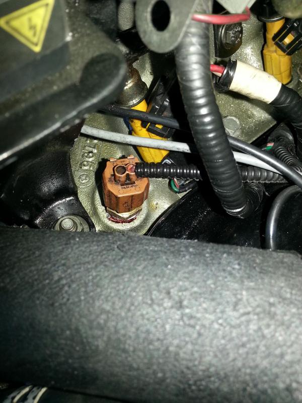
Temp gauge: Reuse the Ranger 2 wire sensor as a 1 wire. Looking into the sensor connector, clip catch on top, use the (NOT left!!!!) right pin in the sensor.
OH SNAP!!!!! JUST DOUBLED CHECKED, IT'S THE RIGHT PIN!!!!!!!!!
Tach: at back of gauge cluster move pin 8 on the 10 pin connector to slot 16 on the 16 pin connector
For my '96 Expo powered '02 I only found a few needed changes: Your 03 should be close.
For the starter -- Ranger end, pin 28 ti ground, Leave Expo end open.
Speedometer signal -- Ranger end, pin 13 open, Expo end to ground.
Also,
Temp gauge: Reuse the Ranger 2 wire sensor as a 1 wire. Looking into the sensor connector, clip catch on top, use the (NOT left!!!!) right pin in the sensor.
OH SNAP!!!!! JUST DOUBLED CHECKED, IT'S THE RIGHT PIN!!!!!!!!!
Tach: at back of gauge cluster move pin 8 on the 10 pin connector to slot 16 on the 16 pin connector
Last edited by win; 01-08-2015 at 04:28 PM.
#18
01-05-2015
Join Date: Aug 2014
Location: Portland, OR
Posts: 93
Likes: 0
Received 0 Likes
on
0 Posts
I don't have a copy of the EVTM for an 03 Ranger.
For my '96 Expo powered '02 I only found a few needed changes: Your 03 should be close.
For the starter -- Ranger end, pin 28 ti ground, Leave Expo end open.
Speedometer signal -- Ranger end, pin 13 open, Expo end to ground.
Also,
Temp gauge: Reuse the Ranger 2 wire sensor as a 1 wire. Looking into the sensor connector, clip catch on top, use the left pin in the sensor.
Tach: at back of gauge cluster move pin 8 on the 10 pin connector to slot 16 on the 16 pin connector
#19
01-05-2015
Join Date: Jan 2014
Location: Tampa, Florida
Posts: 94
Likes: 0
Received 0 Likes
on
0 Posts
The fuel pressures are quite different between the two EFI systems so I chose to remove the higher pressure FPR from the tank and route a length of the original Explorer return line back to the fuel filter and then connect to the Ranger's return at the filter. Bought a generic fuel line repair tube with the correct bulges to snap into the Ranger fittings at the fuel filter. Silver soldered the Expo fuel line into the repair line but a coupling would work as well.
Using a '96 Expo fuel filter -- pops into the original filter bracket just fine.
One caveat -- on the Ranger filter, the center/rear fuel line is the return, the offset/rear fuel line is the supply. On the Expo fuel filter, the inlet is the same size as the Ranger return -- won't work that way!
A pair of 5/16" nylon fuel line couplings to swap the two ends on the two lines was all it too.
One thing I did find was that the OEM and after market FPR's for the Expo fuel rail all ran at the bottom end of the pressure curve. Opted for an adjustable FPR set at the top end of the pressure curve. Fuel trims run -5 to -7% at the higher pressures, nothing the PCM can't handle.
#20
01-05-2015
Join Date: Aug 2014
Location: Portland, OR
Posts: 93
Likes: 0
Received 0 Likes
on
0 Posts
So just so I'm understanding correctly, you kept the Explorer return rails, put the Explorer fuel pressure regulator in the Ranger tank unit (or your adjustable), ran the return line from the rails to a Ranger fuel filter. Is that right? And to simplify it, maybe use the Explorer fuel filter and just get the couplings? Sounds fairly straight forward as far as the fuel goes. What adjustable FPR did you end up going with?
#21
01-05-2015
Join Date: Jan 2014
Location: Tampa, Florida
Posts: 94
Likes: 0
Received 0 Likes
on
0 Posts
Nope, installed an adjustable FPR on the Explorer's fuel rail.
Simply used the removed FPR's fitting in the tank as the fuel return
Ran about half of the Explorer's fuel return line to the area of the fuel filter. (some gentle reshaping needed to follow the contour of the Ranger's fuel supply line.
Installed an Explorer fuel filter
Swapped the Ranger's back of the fuel filter fittings. After swapping, plugged the fuel supply into the back of the Explorer fuel filter and the return line to the tank into the return line from the fuel rail in the engine bay.
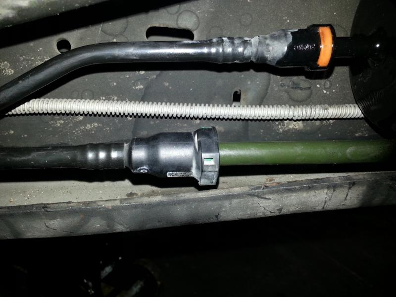
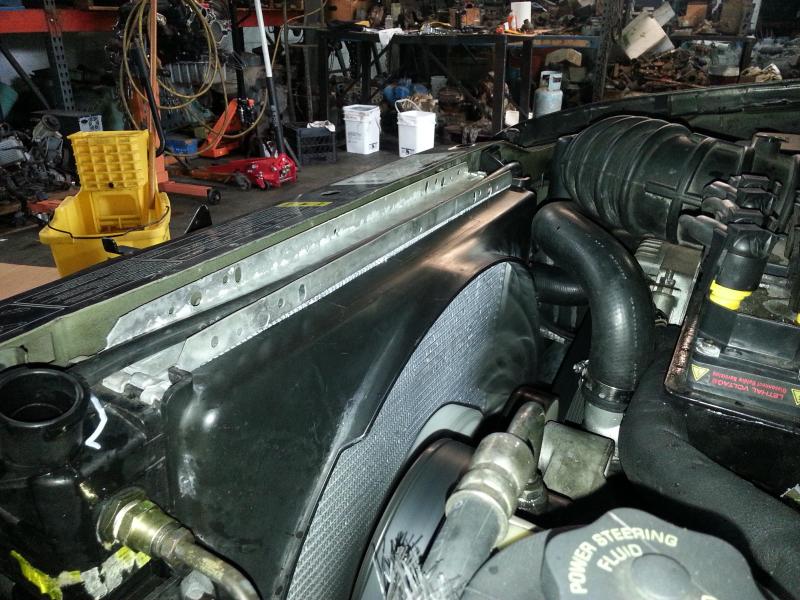
In the pic, the green tube is the generic fuel line repair piece from the local auto parts house, is silver soldered to the Explorer fuel return line from the engine bay. You can see the back of the filter to the upper right.
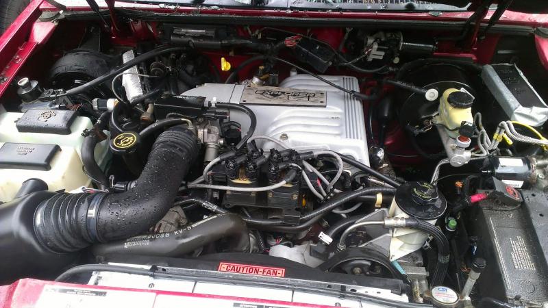
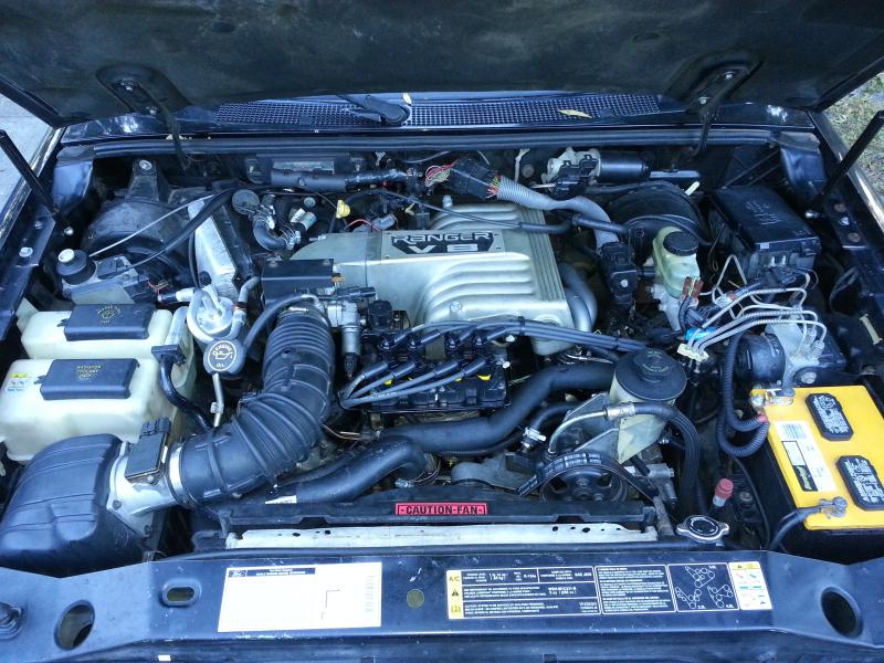
And can't resist, a gratuitous shot of the engine bay. I've since modified the original 3.0 fan shroud to fit the Explorer radiator -- a much better fit than the 5.0 shroud.
and the "improved" fan shroud:
Simply used the removed FPR's fitting in the tank as the fuel return
Ran about half of the Explorer's fuel return line to the area of the fuel filter. (some gentle reshaping needed to follow the contour of the Ranger's fuel supply line.
Installed an Explorer fuel filter
Swapped the Ranger's back of the fuel filter fittings. After swapping, plugged the fuel supply into the back of the Explorer fuel filter and the return line to the tank into the return line from the fuel rail in the engine bay.
In the pic, the green tube is the generic fuel line repair piece from the local auto parts house, is silver soldered to the Explorer fuel return line from the engine bay. You can see the back of the filter to the upper right.
And can't resist, a gratuitous shot of the engine bay. I've since modified the original 3.0 fan shroud to fit the Explorer radiator -- a much better fit than the 5.0 shroud.
and the "improved" fan shroud:
#22
01-05-2015
Join Date: Aug 2014
Location: Portland, OR
Posts: 93
Likes: 0
Received 0 Likes
on
0 Posts
Very nice! Okay, that makes much more sense. The pictures helped out. I've got like 10 tabs open on my browser of things I've been researching, are going to buy, etc... It's all starting to blur together. Is that the factory 5.0 intake? Looks like it may have been from your 3.0? Mine is the cylindrical type as shown in the pic up top.
#23
01-05-2015
Join Date: Jan 2014
Location: Tampa, Florida
Posts: 94
Likes: 0
Received 0 Likes
on
0 Posts
The air filter box and intake tube are from a '98/99 Expo -- simply did not care for the look of the round filter box. The '96 MAF was reused as was the IAT sensor. Did have to plug a hole where a breather tube plugged in but other than that, the bits were a direct fit.
A lot of it was probably the fact that the original 3.0 box was square and the "barrel" really did look alien to me in there! (call it vanity!)
A lot of it was probably the fact that the original 3.0 box was square and the "barrel" really did look alien to me in there! (call it vanity!)
#24
01-05-2015
Join Date: Aug 2014
Location: Portland, OR
Posts: 93
Likes: 0
Received 0 Likes
on
0 Posts
The air filter box and intake tube are from a '98/99 Expo -- simply did not care for the look of the round filter box. The '96 MAF was reused as was the IAT sensor. Did have to plug a hole where a breather tube plugged in but other than that, the bits were a direct fit.
A lot of it was probably the fact that the original 3.0 box was square and the "barrel" really did look alien to me in there! (call it vanity!)
A lot of it was probably the fact that the original 3.0 box was square and the "barrel" really did look alien to me in there! (call it vanity!)
#25
01-06-2015
Join Date: Aug 2014
Location: Portland, OR
Posts: 93
Likes: 0
Received 0 Likes
on
0 Posts
Does anyone have a good suggestion on what cam to go with? I've read A LOT of cam question threads and there is a ton of back and forth on an E letter cam, a couple different comp cams (Comp 35-512-8) and so on... I know I want to throw in a cam, and POSSIBLY new rockers and springs, but not set on that for immediate install since the GT40 can handle a decent lift until I upgrade later.
I'm installing the 99+ manifolds, dual exhaust dumped at the back of the cab (not a daily driver), and maybe an intake. That's all I have planned as of now until I can get some headers to actually flow more air.
I'm installing the 99+ manifolds, dual exhaust dumped at the back of the cab (not a daily driver), and maybe an intake. That's all I have planned as of now until I can get some headers to actually flow more air.


