How-To: Paint your overlays and convert to LEDs
#1
 03-31-2010


How-To: Paint your overlays and convert to LEDs
How-To author: TrePaul86
Original thread: https://www.ranger-forums.com/f59/ho...rt-leds-62796/
Let the modding Begin!!
_________________________
So I started this thread to help answer any and all questions on running a LED setup, one like I have and a how to on how to paint your overlays including how to take them off properly. I'm hoping this will help cut down the questions to John and I. Just want to start it off, I didn't come up with the idea, I got all my overlay information from John, so thanks John!
What's needed:
Total time: about 9-12 hours not including drying time and re assembly after the drying has happened.
I'm going to go ahead and start with the gauges out of the truck. I'm sure you can, at this point, find out how to take them out if you're going to attempt this easy, cheap mod!
There's 7 torx bolts you need to take out with I believe its a t15 head.
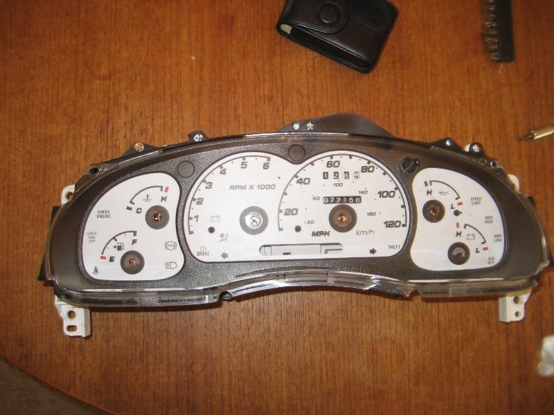
Also when you take the needles off the gauges, use something like a golf ball divot repair tool, this worked well for me. Some may say to use a fork, that also works. BEFORE YOU DO ANY OF THIS, it's best to warm the truck up to the normal operating temperature and either make drawings, or take pictures (this works best) of where the needles sit/lay. Once you pop the needles off this is the only way to get them back in place when you put them back on. I saw to do this when it's warm because that way you can be precise in putting them back where they belong.
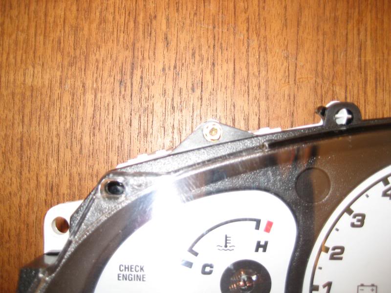
Once you pop the cover off, you have to slide something under the over lays and BE VERY CAREFUL to take your time on this step. You can pull up too hard and kink the overlay and it won't lay flat and screw up the needles. I used my pocket knife, that i've done twice now and it worked awesome.
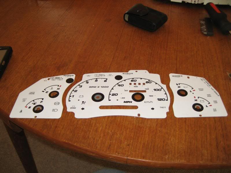
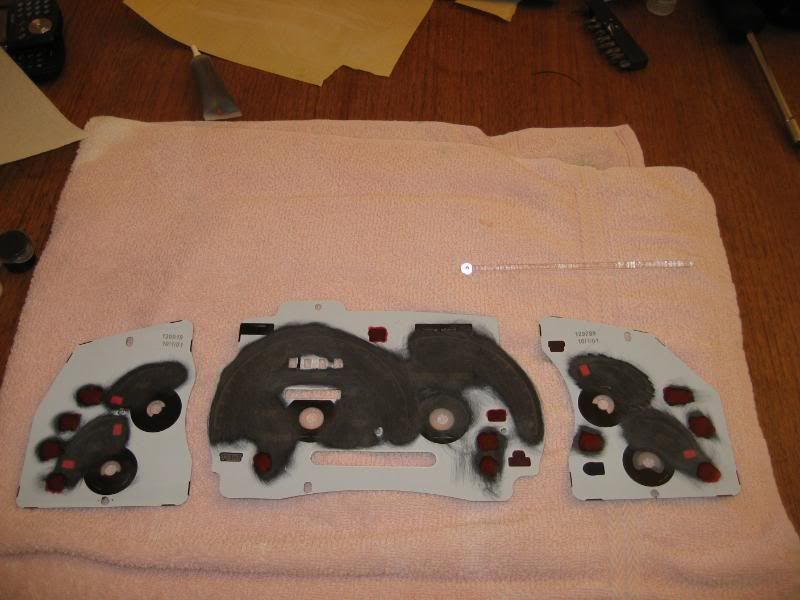
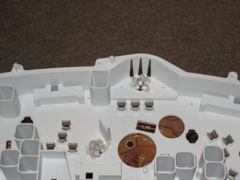
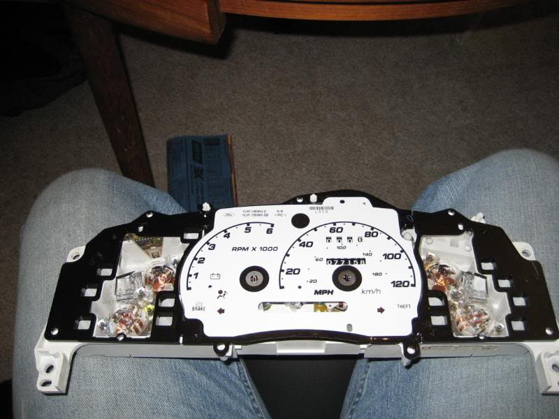
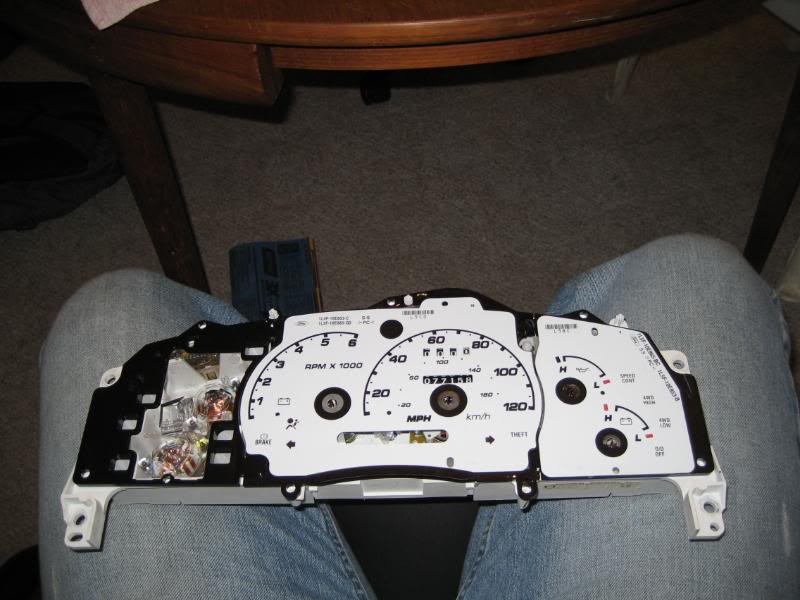
Once you get them off, they'll look like this.
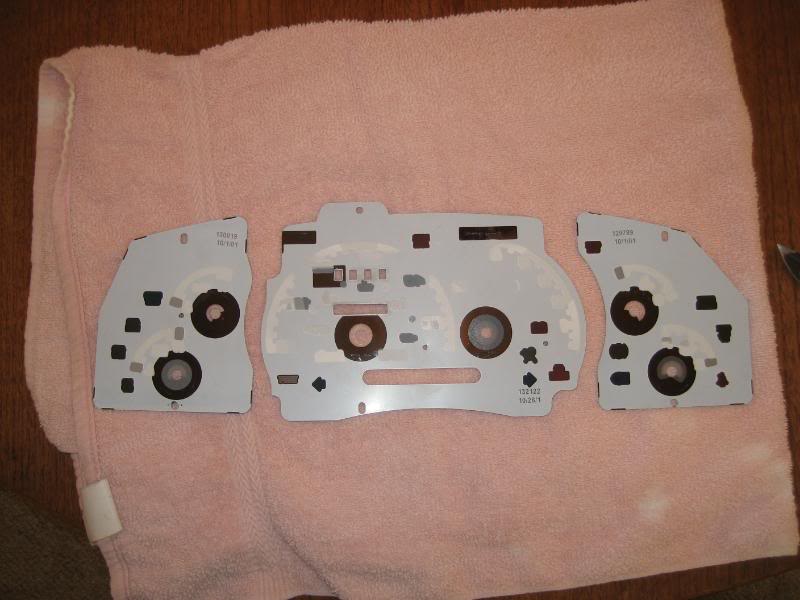
Now I didn't take any pics of me wet sanding the back side of the gauges, but that was a heck of a lot faster than scraping off the all the factory tint with my knife. Just go to the hardware store and pick up an assortment of sand paper, I used 220 grit and wet sanded the gauges. It turned out real nice and makes a real great surface for the glass paint to bond to.
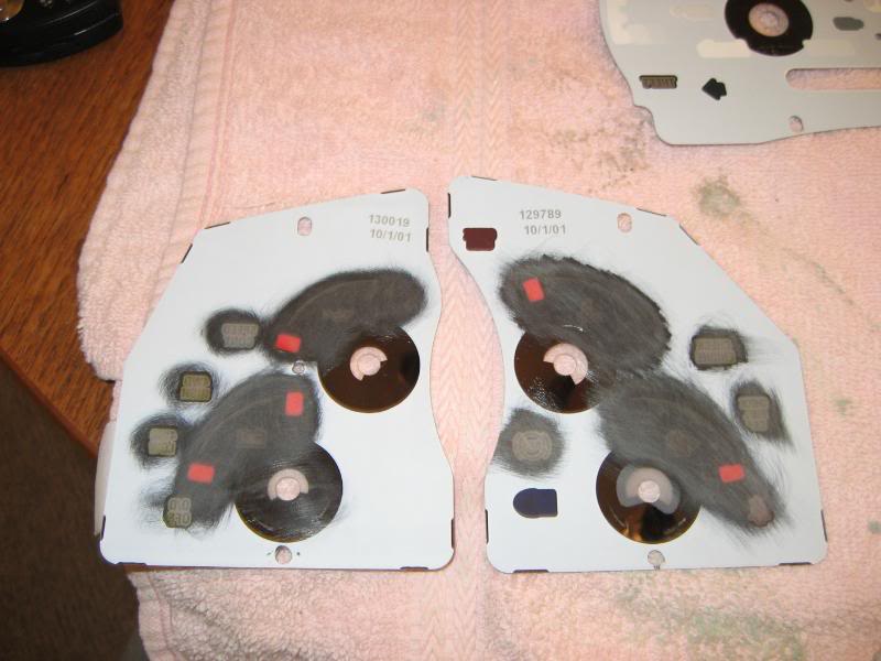
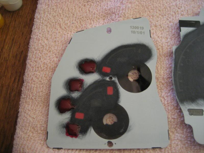
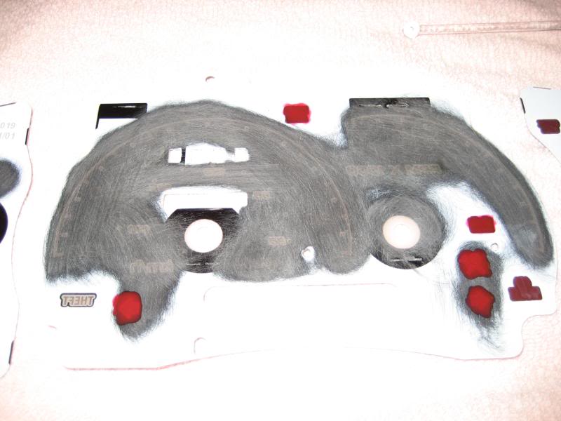
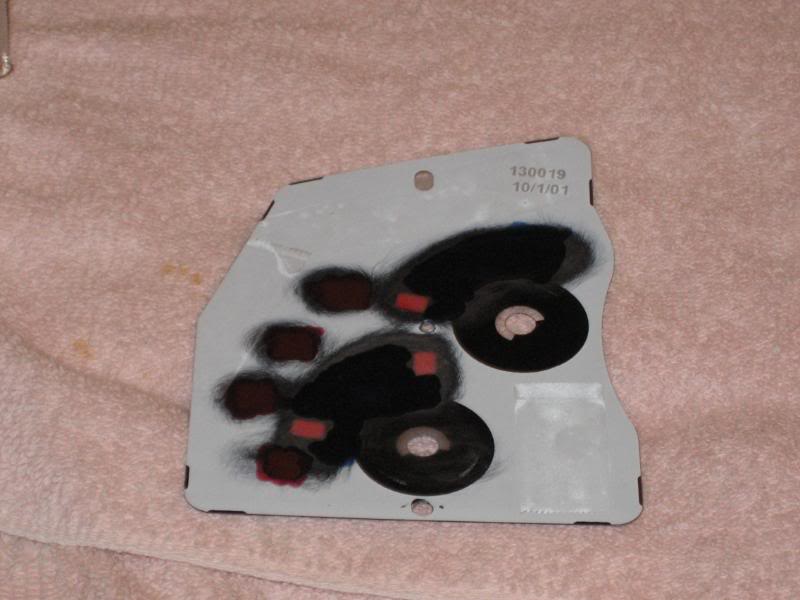
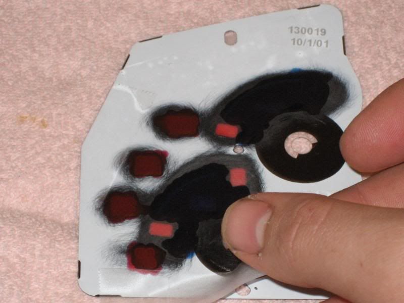
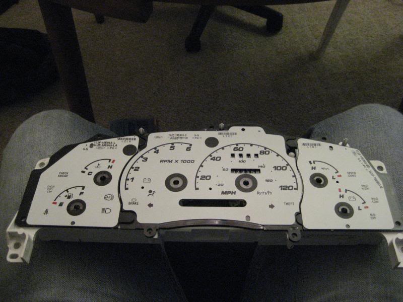
Once you've done this to all three over lay pieces, it should look something like this.
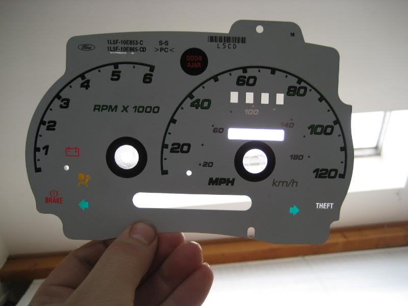
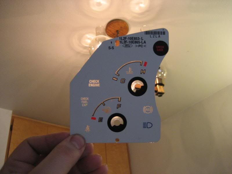
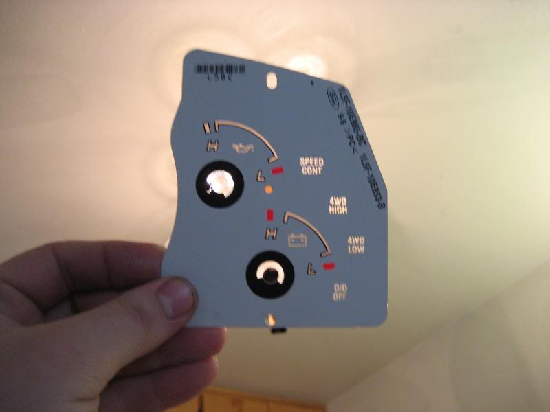
You want to continually check the over lay by holding it up in the light making sure you get all the factory tint off of the over lay other wise you'll end up with uneven coloring with the LEDs and the glass paint, not to mention it will make the tedious job you've done look hack.
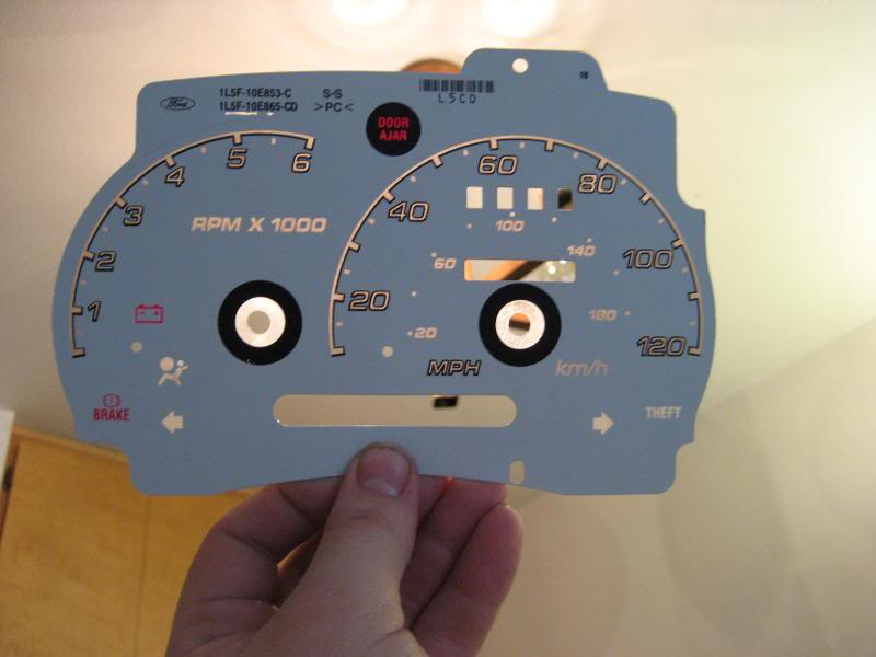
Then once you've done that and are ready for the painting process, make sure you wipe the surface down with some rubbing alcohol to prep it to make sure the paint sticks well to the over lays. Then it's all up to you to decide what you want to show what when a light is behind it. For this setup I'm going to be running all red dummy lights (turn signals, 4wd selector indicators, speed control, seat belt, airbag, ABS, cruise control, battery, brake, check engine, etc) and the speedometer, ammeter, oil pressure, battery, fuel and tachometer will be painted with blue. Just for fun I painted the kmh purple to sort of make it a little bit darker than the mph.
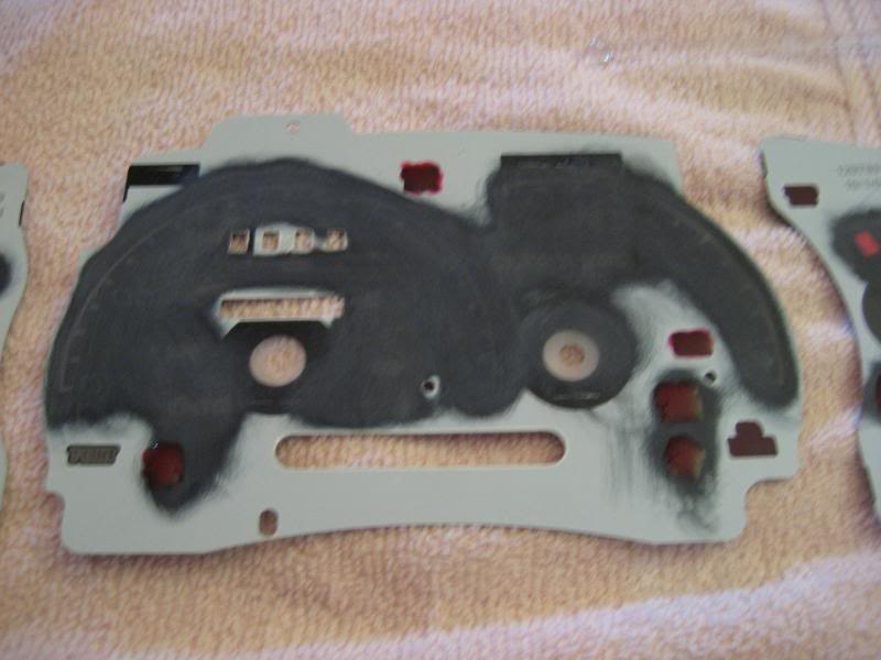
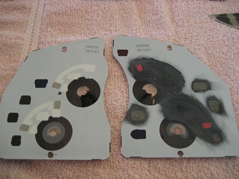
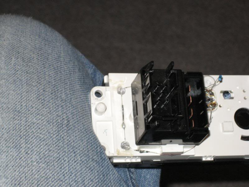
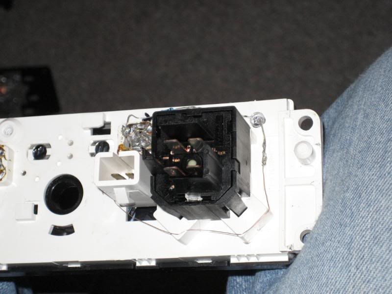
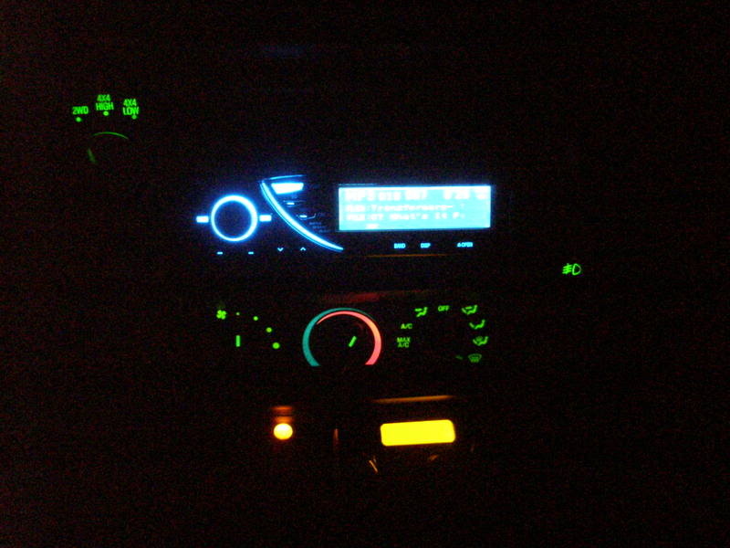
The heater panel works the same way. There's a few ways you can do it, one way is the way I did it by just painting the areas I wanted to show color through the back side of the black plate. The other way is you can actually take the sticky over lay off the front of the panel it self and paint it. I've done it both ways and found it's easier to put the paint on the back side of the black piece leaving the over lays on.
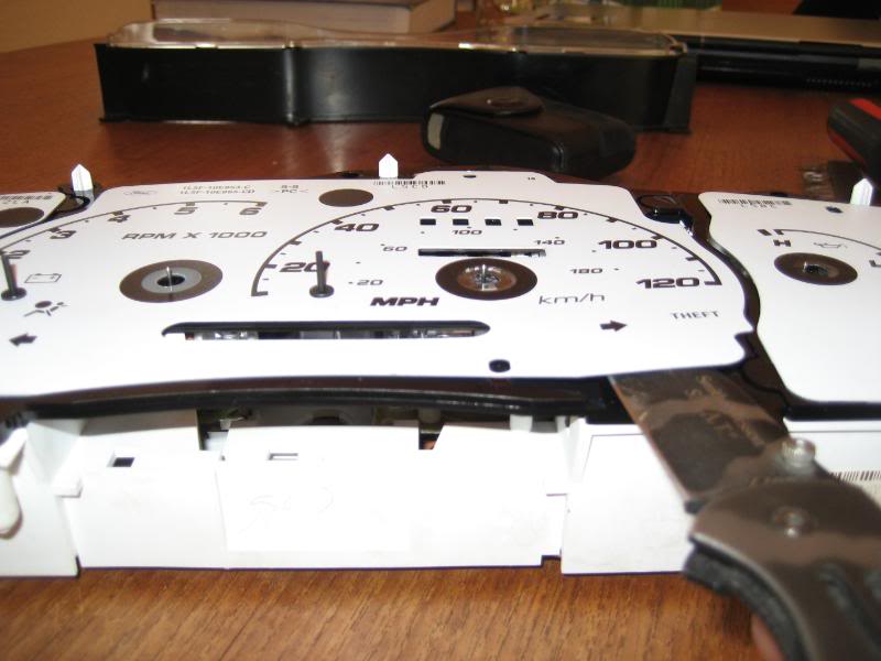
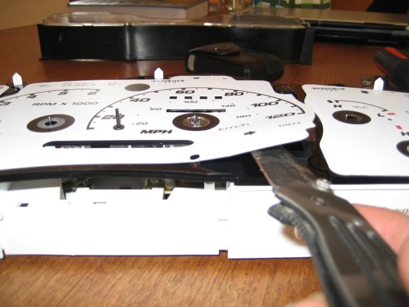
Next you need to pop off the three sections that control all the needles. I didn't take pictures on how to do this, so I'm going to trust you can figure this one out. You start by pulling up on the outside sections (the ammeter gauge and the fuel pressure gauge; and the fuel gauge and water temp gauge). Then it's the same process for removing the middle section with the speedometer and tachometer. Then you're left with the white piece to the gauges where you can get to the very back of the gauge panel and the back side of the gauge panel (where the ribbon is that controls everything).
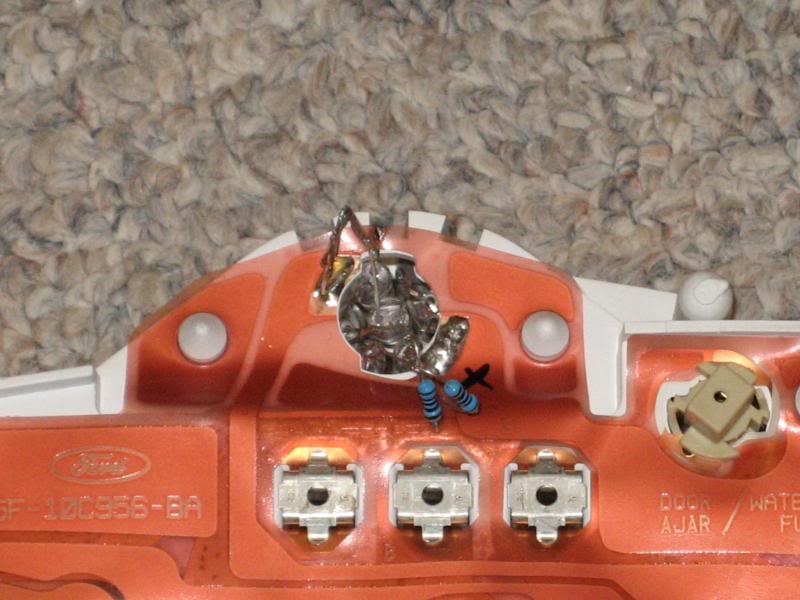
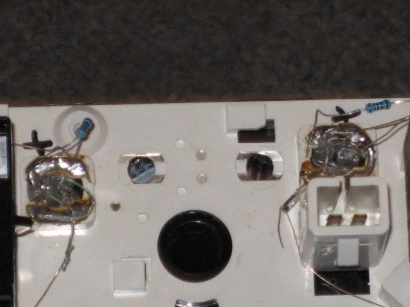
This next part is what may take some time, but knowing how to operate a continuity tester really help out! You need to find out which side of the 6 194 bulb holes is the positive side. Again, this may take some time and you may get frustrated at this part. I marked all the sides with a plus to indicate which side was the positive side. This is vital for installing the LEDs in the right way. LEDs have polarity meaning they will only work with current flowing in one direction. If you hook them up backwards, no worries, nothing will happen, just flip the leads and you'll have power. Important note with LEDs, the longer lead for each LED is the positive lead. This is the lead that gets the resistor.
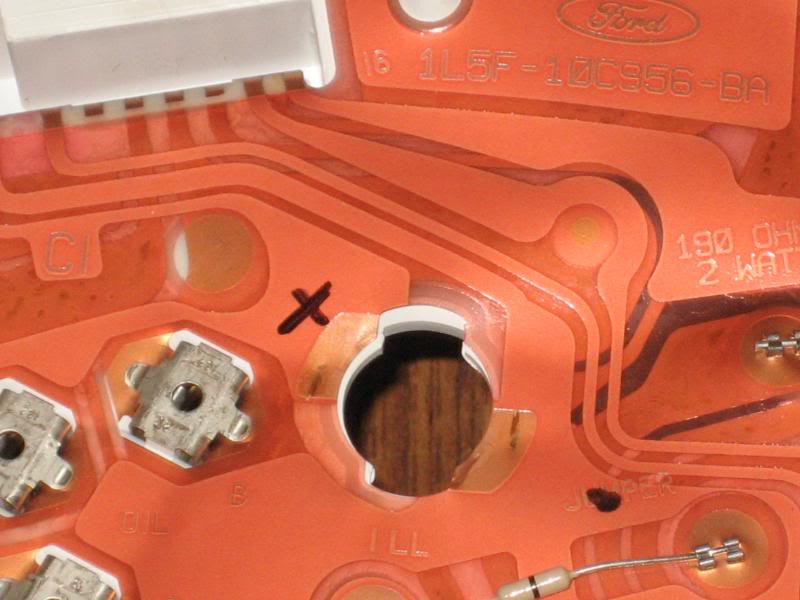
If you can see good enough with the picture, you can go off that gauge exactly if you have the ST gauges like these or the silver 03 gauges. The positive side of each 194 bulb hole is exactly the same.
For this next step, I ran a 5 bulb cluster in my gauges, in this setup I ran 6. To optimize the resistor you can run 3 LEDs in series (resistor soldered to positive and that negative of the LED goes to the positive of another LED, then that negative goes to another positive of the 3rd LED then that negative gets grounded). Proper resistance Ive found is 1/4 watt, 510ohm resistors. Again, they're cheap so just buy a bunch. The leds I used where Shanes 13,000mcd rating 5mm blue LEDs. The trick is to sand down the tip of the LED flat to help dissipate the light evenly; when the LED is not sanded down and the has the rounded tip on it, it creates a beam forward, limiting the surrounding area of light. The 6 LED cluster can look like this, or how ever you want it to look, this is what mine looks like
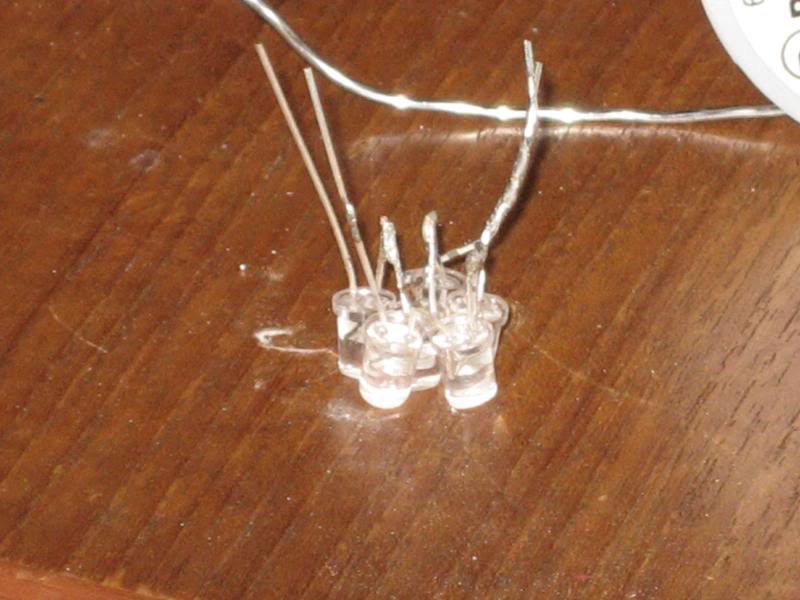
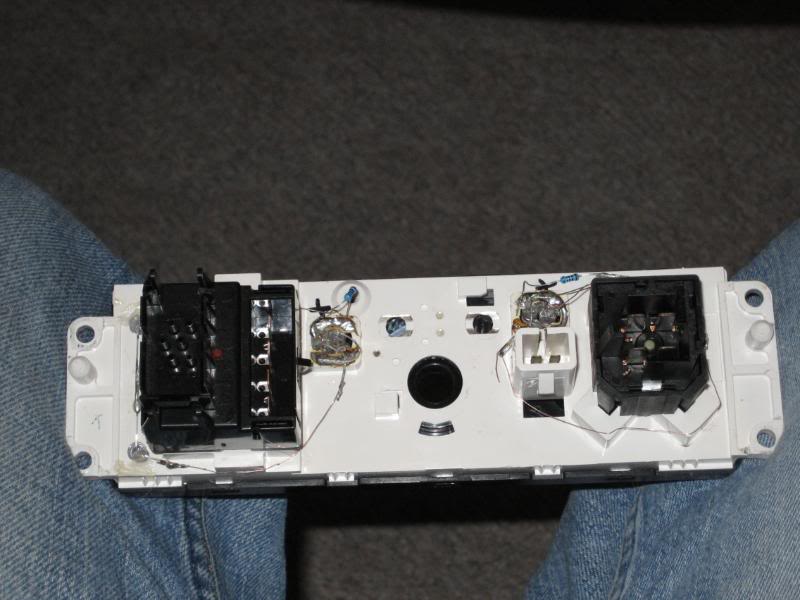
the insert it in from the front towards the back of the gauges and bend the resistor leads and the negative leads and solder them to the board/ribbon to their appropriate lead that you have already marked.
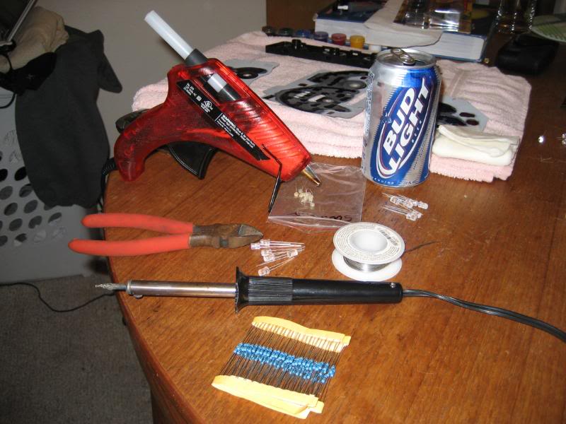
This is a brief picture of what you'll need to do the job lol
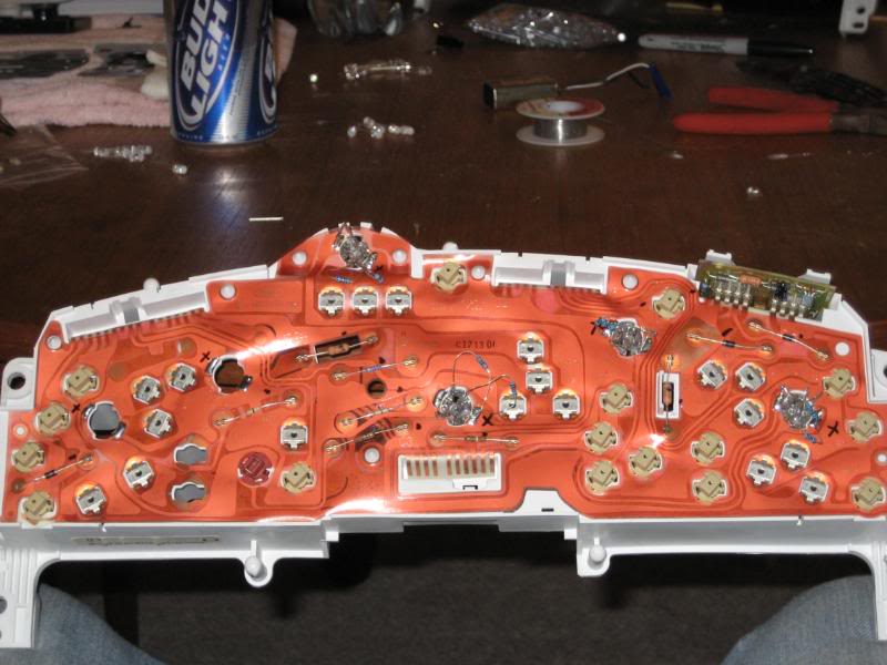
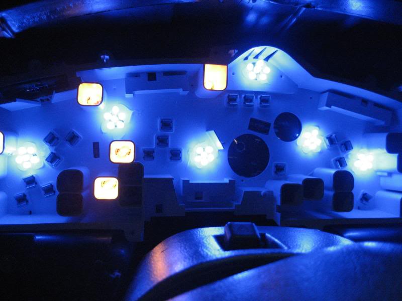
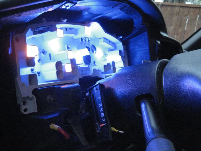
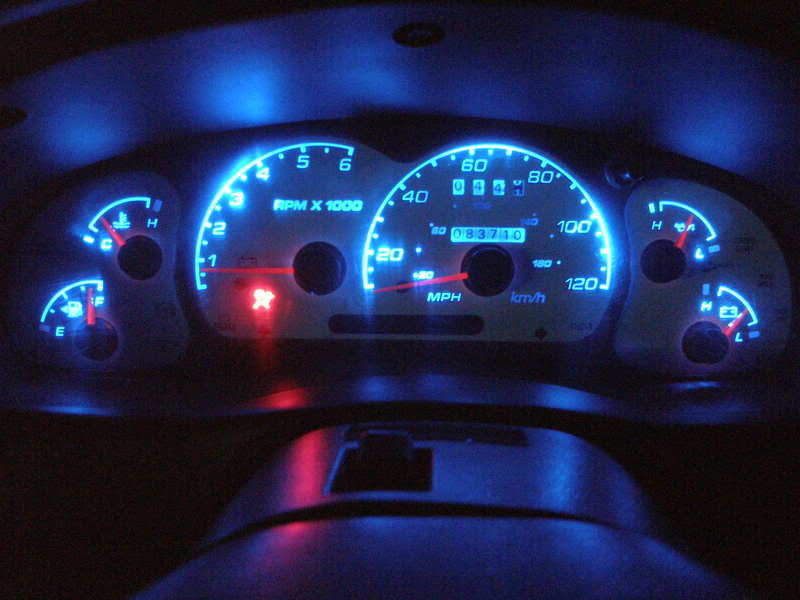
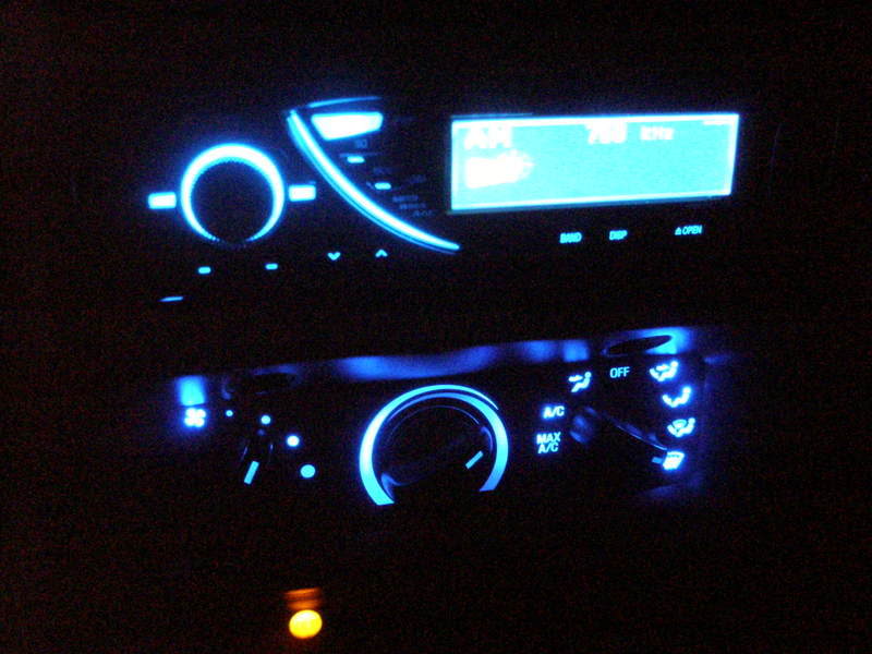
After I finished up all the 6-194 holes with 6-5mm LEDs, I took it outside and tested it. It looks a lot like this when done.
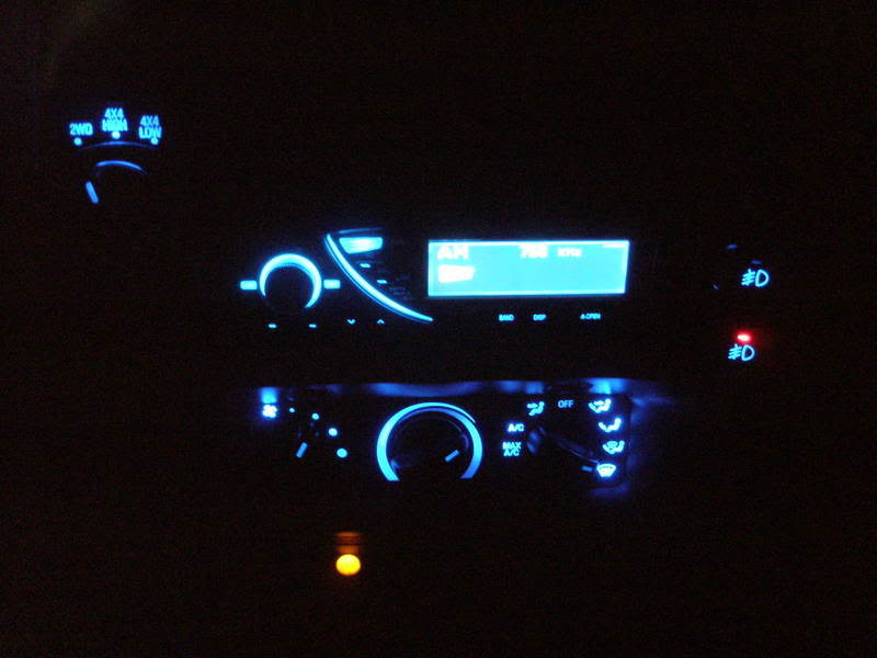
After than I did the same thing to the heater panel, finding out which lead is positive and which one is negative. I ran 3-5mm LEDs in the 2-194 holes on the heater panel and then drilled outside 3 holes around the outsides of the back side of the panel. 2 on the vent selector, one on the top right (looking at the back side) and one on the bottom right to help light those areas. The put one right on the fan of the fan speed selector. After that, I popped it back together.
VERY IMPORTANT!!!
When you finish painting the gauges, let them dry overnight to get a good hard cure of the paint. It takes a good while for this paint to setup and harden so don't rush this at all. If you don't have the patience or don't want to wait, don't tackle this mod. THIS IS VERY IMPORTANT.
After they've dried completely, you'll need some double sided stick tape and place it all over the back side of the gauges. Make sure you don't put it in areas where the LED is going to shine through, it may cause some funny lines and uneven lighting. Line them back up where you took them off. It may help best to use a sharpie and make a small line across the gauge (with the cover off) to help you line it back up where it was before you took it off. Pop the needles back on, but it's best to do this by starting the truck, plugging in the gauges and letting the truck warm up. Then refer to your drawing to make the appropriate sticks for the needles. The speedometer is the tricky one. It's best to go 20mpg or so and stick the needle on lightly until you've got it dead on while you're goin 20, then press it down, but not too far because you don't want it to grab the gauge and have the needle get stuck.
Once you've done that you're home free. Put the cover back on and bolt everything back down and put everything back and you're done!
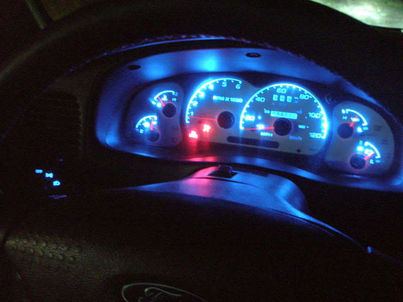
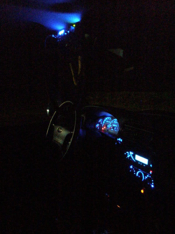
Before:
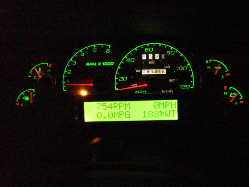
After:
Original thread: https://www.ranger-forums.com/f59/ho...rt-leds-62796/
Let the modding Begin!!
_________________________
So I started this thread to help answer any and all questions on running a LED setup, one like I have and a how to on how to paint your overlays including how to take them off properly. I'm hoping this will help cut down the questions to John and I. Just want to start it off, I didn't come up with the idea, I got all my overlay information from John, so thanks John!
What's needed:
- 7mm socket to remove bolts to get to the gauges
- T15 torx head
- Assortment of sand paper (100-2000grit, depends on how you want yours to turn out)
- Rubbing alcohol
- Transparent glass paint
- 5mm LEDs (# depends on how many you want to wire in)
- 510ohm resistors (They're cheap, just buy 100 or so, usually like $3.50 shipped on eBay)
- Hot glue gun
- Soldering Iron
- Solder
- Double sided stick tape
- Beer (
 )
)
Total time: about 9-12 hours not including drying time and re assembly after the drying has happened.
I'm going to go ahead and start with the gauges out of the truck. I'm sure you can, at this point, find out how to take them out if you're going to attempt this easy, cheap mod!
There's 7 torx bolts you need to take out with I believe its a t15 head.
Also when you take the needles off the gauges, use something like a golf ball divot repair tool, this worked well for me. Some may say to use a fork, that also works. BEFORE YOU DO ANY OF THIS, it's best to warm the truck up to the normal operating temperature and either make drawings, or take pictures (this works best) of where the needles sit/lay. Once you pop the needles off this is the only way to get them back in place when you put them back on. I saw to do this when it's warm because that way you can be precise in putting them back where they belong.
Once you pop the cover off, you have to slide something under the over lays and BE VERY CAREFUL to take your time on this step. You can pull up too hard and kink the overlay and it won't lay flat and screw up the needles. I used my pocket knife, that i've done twice now and it worked awesome.
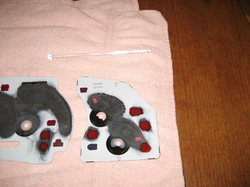
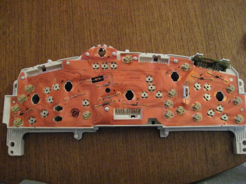
Once you get them off, they'll look like this.
Now I didn't take any pics of me wet sanding the back side of the gauges, but that was a heck of a lot faster than scraping off the all the factory tint with my knife. Just go to the hardware store and pick up an assortment of sand paper, I used 220 grit and wet sanded the gauges. It turned out real nice and makes a real great surface for the glass paint to bond to.
Once you've done this to all three over lay pieces, it should look something like this.
You want to continually check the over lay by holding it up in the light making sure you get all the factory tint off of the over lay other wise you'll end up with uneven coloring with the LEDs and the glass paint, not to mention it will make the tedious job you've done look hack.
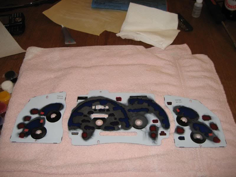
Then once you've done that and are ready for the painting process, make sure you wipe the surface down with some rubbing alcohol to prep it to make sure the paint sticks well to the over lays. Then it's all up to you to decide what you want to show what when a light is behind it. For this setup I'm going to be running all red dummy lights (turn signals, 4wd selector indicators, speed control, seat belt, airbag, ABS, cruise control, battery, brake, check engine, etc) and the speedometer, ammeter, oil pressure, battery, fuel and tachometer will be painted with blue. Just for fun I painted the kmh purple to sort of make it a little bit darker than the mph.
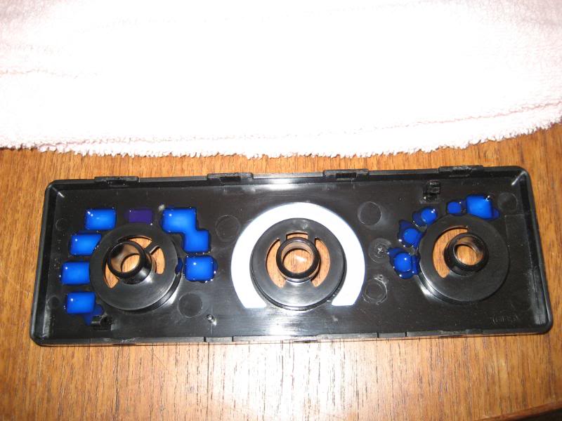
The heater panel works the same way. There's a few ways you can do it, one way is the way I did it by just painting the areas I wanted to show color through the back side of the black plate. The other way is you can actually take the sticky over lay off the front of the panel it self and paint it. I've done it both ways and found it's easier to put the paint on the back side of the black piece leaving the over lays on.
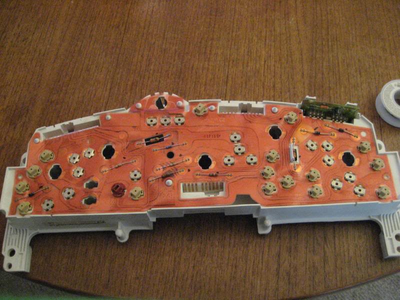
Next you need to pop off the three sections that control all the needles. I didn't take pictures on how to do this, so I'm going to trust you can figure this one out. You start by pulling up on the outside sections (the ammeter gauge and the fuel pressure gauge; and the fuel gauge and water temp gauge). Then it's the same process for removing the middle section with the speedometer and tachometer. Then you're left with the white piece to the gauges where you can get to the very back of the gauge panel and the back side of the gauge panel (where the ribbon is that controls everything).
This next part is what may take some time, but knowing how to operate a continuity tester really help out! You need to find out which side of the 6 194 bulb holes is the positive side. Again, this may take some time and you may get frustrated at this part. I marked all the sides with a plus to indicate which side was the positive side. This is vital for installing the LEDs in the right way. LEDs have polarity meaning they will only work with current flowing in one direction. If you hook them up backwards, no worries, nothing will happen, just flip the leads and you'll have power. Important note with LEDs, the longer lead for each LED is the positive lead. This is the lead that gets the resistor.
If you can see good enough with the picture, you can go off that gauge exactly if you have the ST gauges like these or the silver 03 gauges. The positive side of each 194 bulb hole is exactly the same.
For this next step, I ran a 5 bulb cluster in my gauges, in this setup I ran 6. To optimize the resistor you can run 3 LEDs in series (resistor soldered to positive and that negative of the LED goes to the positive of another LED, then that negative goes to another positive of the 3rd LED then that negative gets grounded). Proper resistance Ive found is 1/4 watt, 510ohm resistors. Again, they're cheap so just buy a bunch. The leds I used where Shanes 13,000mcd rating 5mm blue LEDs. The trick is to sand down the tip of the LED flat to help dissipate the light evenly; when the LED is not sanded down and the has the rounded tip on it, it creates a beam forward, limiting the surrounding area of light. The 6 LED cluster can look like this, or how ever you want it to look, this is what mine looks like
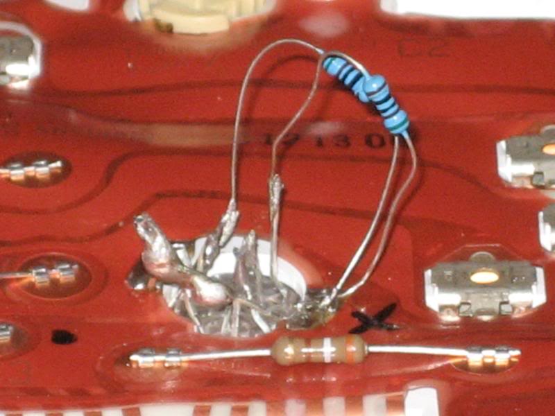
the insert it in from the front towards the back of the gauges and bend the resistor leads and the negative leads and solder them to the board/ribbon to their appropriate lead that you have already marked.
This is a brief picture of what you'll need to do the job lol
After I finished up all the 6-194 holes with 6-5mm LEDs, I took it outside and tested it. It looks a lot like this when done.
After than I did the same thing to the heater panel, finding out which lead is positive and which one is negative. I ran 3-5mm LEDs in the 2-194 holes on the heater panel and then drilled outside 3 holes around the outsides of the back side of the panel. 2 on the vent selector, one on the top right (looking at the back side) and one on the bottom right to help light those areas. The put one right on the fan of the fan speed selector. After that, I popped it back together.
VERY IMPORTANT!!!
When you finish painting the gauges, let them dry overnight to get a good hard cure of the paint. It takes a good while for this paint to setup and harden so don't rush this at all. If you don't have the patience or don't want to wait, don't tackle this mod. THIS IS VERY IMPORTANT.
After they've dried completely, you'll need some double sided stick tape and place it all over the back side of the gauges. Make sure you don't put it in areas where the LED is going to shine through, it may cause some funny lines and uneven lighting. Line them back up where you took them off. It may help best to use a sharpie and make a small line across the gauge (with the cover off) to help you line it back up where it was before you took it off. Pop the needles back on, but it's best to do this by starting the truck, plugging in the gauges and letting the truck warm up. Then refer to your drawing to make the appropriate sticks for the needles. The speedometer is the tricky one. It's best to go 20mpg or so and stick the needle on lightly until you've got it dead on while you're goin 20, then press it down, but not too far because you don't want it to grab the gauge and have the needle get stuck.
Once you've done that you're home free. Put the cover back on and bolt everything back down and put everything back and you're done!
Before:
After:
Last edited by 98liftedranger; 11-27-2011 at 09:47 PM.
#2
07-12-2016

Join Date: Apr 2016
Location: Jackson
Posts: 106
Likes: 0
Received 0 Likes
on
0 Posts
#3
07-12-2016

I'm not the OP, but I can offer some insight none the less.
He painted the HVAC like he did the gauge cluster, as shown in a couple of photos. Chances are is he did the same thing for the switches.
Being honest, though, that's a lot more difficult than what it has to be. The end result is very nice, but there's easier ways.
For the 4wd switch, you can fairly easily pop the switch apart and solder a few LEDs in on the contacts. The bulb is a regular incandecent bulb with a colored rubber boot over the bulb itself to give it the color. Unfortunately no plug and play solution exists at this point for the 4wd switch as it is horribly tall and ford specific. In my 4WD switch, I used a color changing RGB LED with no paint and it works just fine.
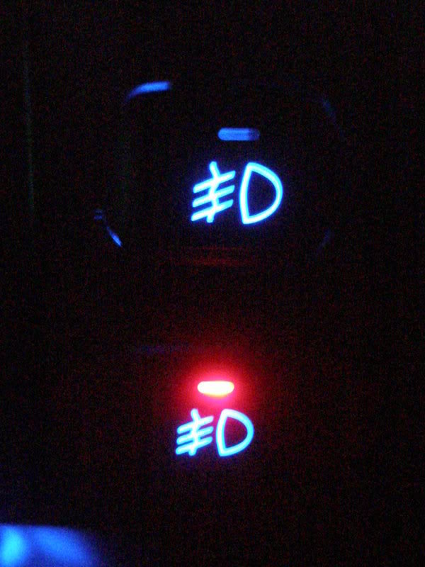
The fog light switch though is much easier, though. On the side of the switch, there's another twist lock bulb with a rubber boot to determine its color. Thankfully, premade solutions exist for this one. I purchased mine on superbrightleds.com, but you can probably find them on amazon or ebay, too. I forget the number for the bulb, but it's fairly simple to match up the OEM bulb to what you find online, no paint required.
Like the fog light switch, same theory applies to literally everything else. In fact, the headlight switch can be done in the same way the 4wd switch. Just, be careful when taking them apart. There's ball bearings inside them.
I would like to note that I'm not putting this method (shown above) down. It's a perfectly suitable method; but none the less there's other (easier) ways that produce the same result.
He painted the HVAC like he did the gauge cluster, as shown in a couple of photos. Chances are is he did the same thing for the switches.
Being honest, though, that's a lot more difficult than what it has to be. The end result is very nice, but there's easier ways.
For the 4wd switch, you can fairly easily pop the switch apart and solder a few LEDs in on the contacts. The bulb is a regular incandecent bulb with a colored rubber boot over the bulb itself to give it the color. Unfortunately no plug and play solution exists at this point for the 4wd switch as it is horribly tall and ford specific. In my 4WD switch, I used a color changing RGB LED with no paint and it works just fine.
The fog light switch though is much easier, though. On the side of the switch, there's another twist lock bulb with a rubber boot to determine its color. Thankfully, premade solutions exist for this one. I purchased mine on superbrightleds.com, but you can probably find them on amazon or ebay, too. I forget the number for the bulb, but it's fairly simple to match up the OEM bulb to what you find online, no paint required.
Like the fog light switch, same theory applies to literally everything else. In fact, the headlight switch can be done in the same way the 4wd switch. Just, be careful when taking them apart. There's ball bearings inside them.
I would like to note that I'm not putting this method (shown above) down. It's a perfectly suitable method; but none the less there's other (easier) ways that produce the same result.
#4
07-13-2016
Join Date: Apr 2016
Location: Jackson
Posts: 106
Likes: 0
Received 0 Likes
on
0 Posts
Thanks man, I agree there are easier methods, trust me I've been looking intensively on doing this project on my 2nd gen explorer (used to have a ranger but totaled it a few weeks ago) and I have been finding different ways, but I have to take apart the dash anyway to fix the oil pressure needle so this might be my decision since I will be in there anyway.
#5
10-12-2019

I did this to my 98 and used blue LEDd. Now that I have my 99 4x4 I want to do it again. However, I want to do something a little different. I was wondering if anyone has tried needles from a different vehicle. I like the needles in my wife's 2013 Focus. Does anyone know if these needles, or any other needles will work as a direct replacements? Do y'all think white lights on white gauges (assorted painted areas) would look to washed out? Thanks.

Thread
Thread Starter
Forum
Replies
Last Post
Jp7
General Technical & Electrical
23
04-22-2021 09:48 PM
For Sale: h11 leds with 68 leds in each light - GA
imprezu
OLD - Interior, Exterior, Electrical, & Misc.
12
10-21-2010 11:27 AM
FMD
General Ford Ranger Discussion
10
12-31-2006 01:44 PM


