How-To: OE Foglight Switch with Aftermarket Lights
#1
 09-05-2010


How-To: OE Foglight Switch with Aftermarket Lights
Let the modding Begin!!
First off--Thanks to Bob-rwenzing-for helping me with the wiring diagram and notes for this install. I was really stuck until I got his input.
Second--after I started this mod, Buggman started selling pre-wired pigtails to accomplish this mod. If you don't feel comfortable doing this mod my way, give him a shout-his set-up is pretty much "plug-and-play" and he does nice work.
Third--this works fine for me, and I'm very comfortable and competent with electrical work, but if you decide to do this mod, do so at your own risk.
Fourth--I did this mod with some KC 100W SlimLites driving lights. It should work fine with other brands, but the wiring colors listed will be different.
Parts List:
Misc crimp connectors: butts, male, female, splice, ring. Red, Blue, and Yellow. Don't skimp on these-buy good ones (3M)!!
Fuse Holder with 5A fuse.
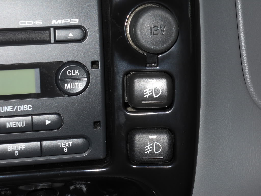
Factory fog light switch with pigtail.
Bezel modded to fit second switch.
Heat shrink tubing.
Split wire loom.
Battery Doctor Tap/Ground Kit--I got mine at Advanced Auto Parts.
Fog Lights/Driving Lights/Long-range Lights. With wiring harness & relay!
Wire stripper, crimping tool, dikes, heat gun (for heat shrink).
Zip Ties-and lots of 'em.
Misc. metric sockets and/or wrenches
NOW--ON TO THE FUN!!!
1) Start by unhooking the negative battery terminal and remove any jewelry--if you have to ask why, you don't know anybody who's tried to arc-weld a wrench to his wedding ring!
2) Run all of the wiring according to the instructions that came with your lights, but don't hook anything up.
3) KC's wiring harness comes with a nice plug that plugs into the relay, too bad you need to cut it off now. Cut it as close to the connector as you can so you have plenty of wire to work with.
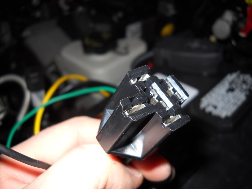
4) I wrapped a piece of electrical tape around my relay and marked the terminal numbers on each side just to keep everything straight.
5) Run the yellow wire with the 20A fuse holder and ring terminal along the side of the battery. Take the fuse out for now. Loosen and remove the POS battery terminal bolt, install the ring terminal onto the bolt, and tighten. Make sure that any ring terminal that was on the POS terminal when you removed the bolt is back on it for obvious reasons.
Install a piece of heat shrink tubing (HST) and a blue female crimp terminal (FCT) onto the cut end. This goes to terminal #30 on the relay.
6) The 2 RED wires that go out each light are next. Strip about 3/8" from each wire, twist them together, install a piece of HST and crimp on a yellow FCT. This will get plugged onto terminal # 87 on the relay, but not yet. Use a blue Scotchlok splice connector to splice a lead from the fuse holder into one of the leads for the lights. This will be the power source for the indicator on the foglight switch. Install a 5A fuse into fuseholder. The original KC pigtail has a fuseholder on the end of the WHITE wire, and was tapped into either the low beam (fog lights) or high beams (driving lights) at the headlight socket. Cut this wire BEHIND the fuseholder, leaving about 6" of wire for the fuseholder. Use a blue butt connector and HST to hook the other end of the fuse holder to the WHITE wire going into the cab.
7) Strip the 2 BLACK wires going out to the lights, and install HST and a yellow FCT. Attach the "Battery Doctor Tap/Ground Kit" onto the chassis ground right above the back of the driver's side headlight. Attach the ground lead for the lights to one of the tabs.
8) Install blue FCT and HST onto GREEN wire going into the cab. Plug onto terminal #85 of the relay. This is the actual "switching" wire.
9) Tap into the back of the headlight socket for the "positive trigger" for the relay using the portion of the white wire-with fuseholder-left over from step #6. Use a blue Scotchlok splice connector for this. At the end behind the fuseholder, install a piece of HST and a blue FCT. Install onto terminal #86 on the relay. There should be a 3A fuse in the fuseholder.
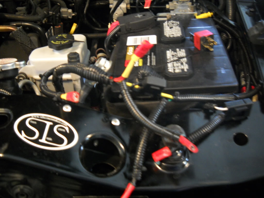
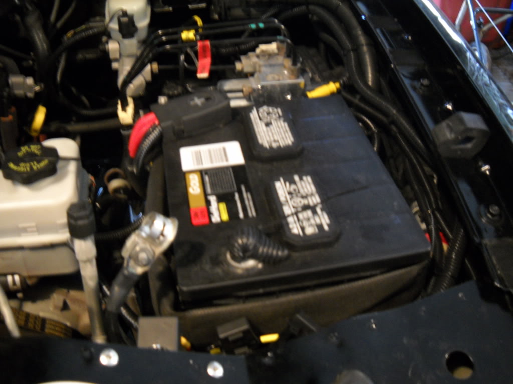
Here are all of my connections with tape on the connectors to mark where they go on the relay. You'll also notice that everything is run in wire loom. I like to keep my wiring jobs neat and professional looking-plus it helps protect the wires.
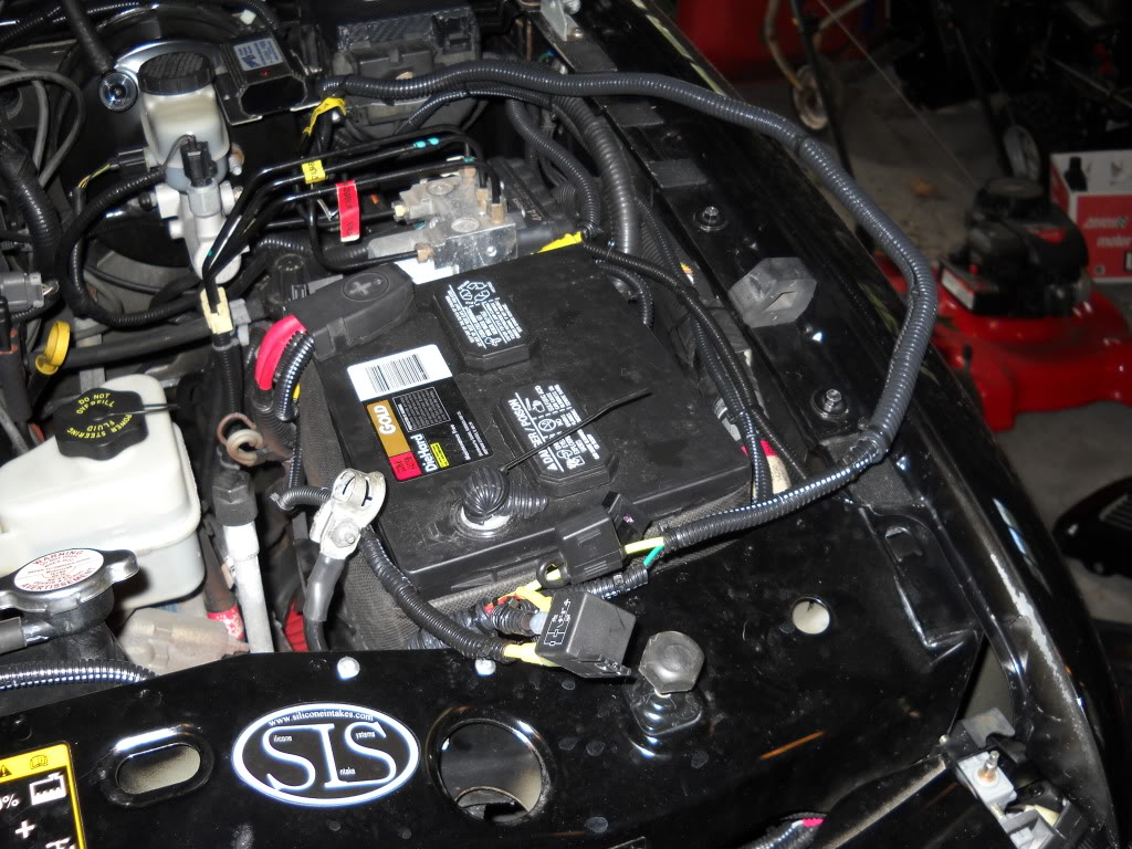
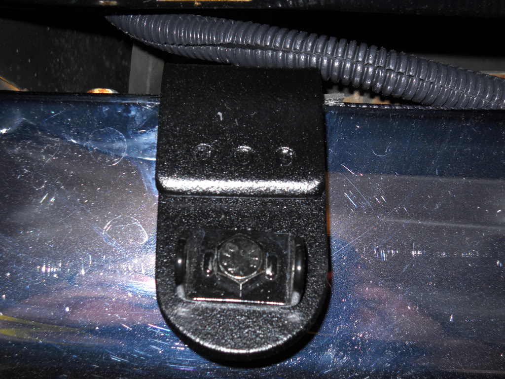
I mounted my relay to a piece of aluminum that I bent 90-degrees and rivetet to the radiator core support where it's easy to access.
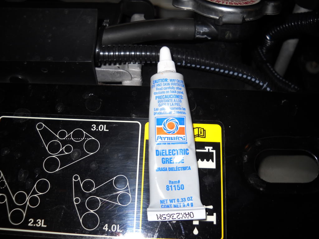
Do yourself a favor, and use some dielectric grease in all of you relay connections.
10) Feed the white and green wires into the cab (if you haven't already) through a firewall grommet. I used a fine piece of wire fed thru the grommet from the cab into the engine compartment, taped the wires to it, and then slowly pulled them into the cab. Run the wires along the bottom of the dashboard and secure with zip ties.
11) Remove your radio and radio bezel, unhook all of the connectors. If you don't have one of these:

-you'd better get to modifying one PRONTO! That's the whole point of this mod!!!

12) Feed the GREEN & WHITE wires up into the area vacated by your radio and crimp either a butt connector or a blue FCT onto each.
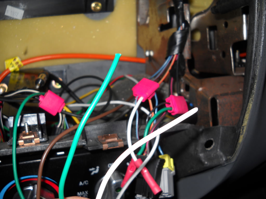
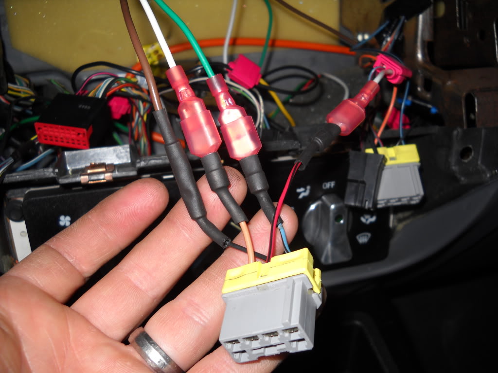
13) Crimp a red male crimp terminal onto the light blue/black and the tan/orange wires for the foglight switch pigtail. Make you connections. GREEN goes to LB/BK, WHITE goes to TN/OR.
14) Use a Scotchlok splice connector to tap the light blue/red from the pigtail into the LB/R wire from the existing switch.
15) Use a short piece of wire with a ring terminal on one end and hook to an exsisting bolt or screw for a ground. Make sure that you check this with your voltmeter. Use a red butt connector to connect to the black wire on the pigtail.
16) Double check all of you connections. Once you're satisfied that all of your wiring is in good shape, reinstall the 20A fuse in the YELLOW wire at the battery (step #5), the 5A fuse for the WHITE lead (step #6), and the 3A fuse coming out of the headlight connector (step #9).
17) Hook up the negative battery terminal.
18) Hook up the lights to the leads if you haven't already.
19) Turn on the headlights--high beams for driving lights, low beams for fog lights.
20) PUSH THAT BUTTON!!!
21) If you've followed these directions, and done a good job with your considerable wiring skills, you will be greeted with wondrous beams of light eminating from the previously darkened glass orbs attached to your truck. And what's that--a glowing LED indicator in the factory switch letting you know that your lights are on?
22) NOW you can put everything back together.
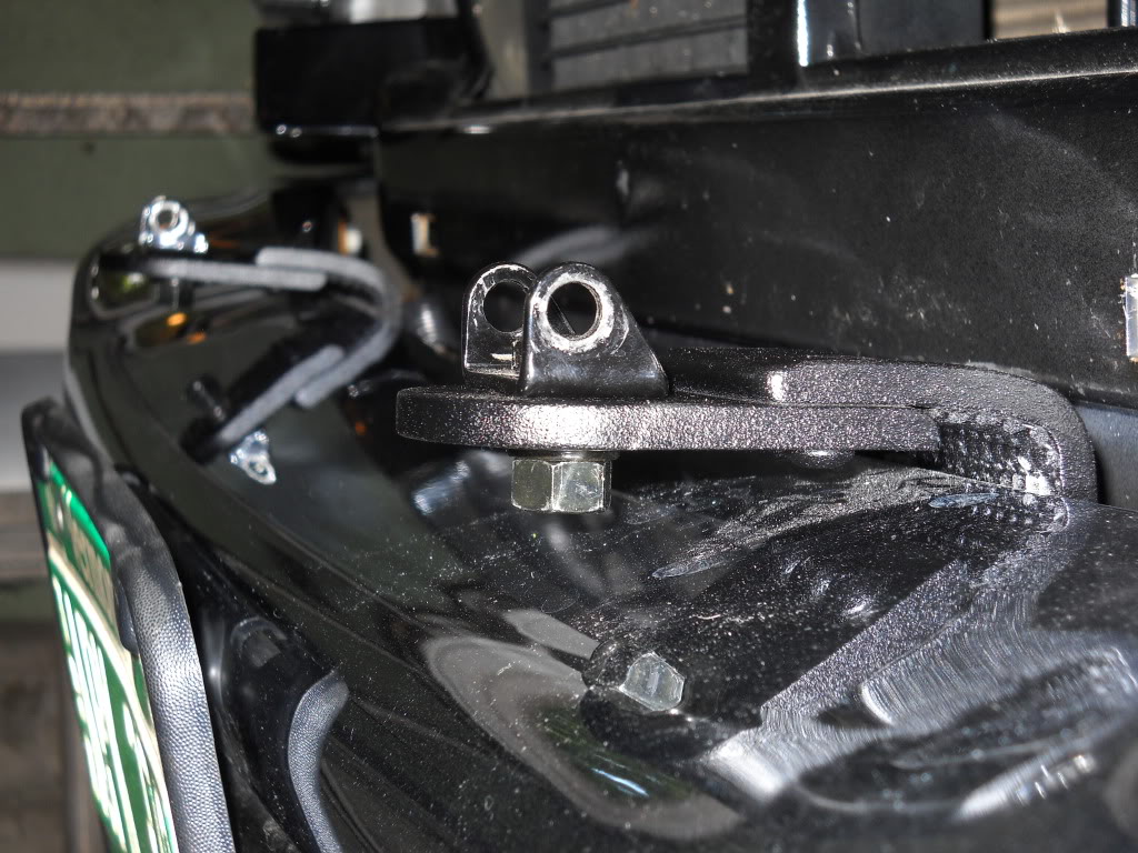
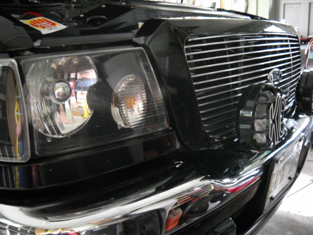
Heres my setup, along with the brackets I fabbed-up:
MikeR
First off--Thanks to Bob-rwenzing-for helping me with the wiring diagram and notes for this install. I was really stuck until I got his input.
Second--after I started this mod, Buggman started selling pre-wired pigtails to accomplish this mod. If you don't feel comfortable doing this mod my way, give him a shout-his set-up is pretty much "plug-and-play" and he does nice work.
Third--this works fine for me, and I'm very comfortable and competent with electrical work, but if you decide to do this mod, do so at your own risk.
Fourth--I did this mod with some KC 100W SlimLites driving lights. It should work fine with other brands, but the wiring colors listed will be different.
Parts List:
Misc crimp connectors: butts, male, female, splice, ring. Red, Blue, and Yellow. Don't skimp on these-buy good ones (3M)!!
Fuse Holder with 5A fuse.
Factory fog light switch with pigtail.
Bezel modded to fit second switch.
Heat shrink tubing.
Split wire loom.
Battery Doctor Tap/Ground Kit--I got mine at Advanced Auto Parts.
Fog Lights/Driving Lights/Long-range Lights. With wiring harness & relay!
Wire stripper, crimping tool, dikes, heat gun (for heat shrink).
Zip Ties-and lots of 'em.
Misc. metric sockets and/or wrenches
NOW--ON TO THE FUN!!!
1) Start by unhooking the negative battery terminal and remove any jewelry--if you have to ask why, you don't know anybody who's tried to arc-weld a wrench to his wedding ring!
2) Run all of the wiring according to the instructions that came with your lights, but don't hook anything up.
3) KC's wiring harness comes with a nice plug that plugs into the relay, too bad you need to cut it off now. Cut it as close to the connector as you can so you have plenty of wire to work with.
4) I wrapped a piece of electrical tape around my relay and marked the terminal numbers on each side just to keep everything straight.
5) Run the yellow wire with the 20A fuse holder and ring terminal along the side of the battery. Take the fuse out for now. Loosen and remove the POS battery terminal bolt, install the ring terminal onto the bolt, and tighten. Make sure that any ring terminal that was on the POS terminal when you removed the bolt is back on it for obvious reasons.
Install a piece of heat shrink tubing (HST) and a blue female crimp terminal (FCT) onto the cut end. This goes to terminal #30 on the relay.
6) The 2 RED wires that go out each light are next. Strip about 3/8" from each wire, twist them together, install a piece of HST and crimp on a yellow FCT. This will get plugged onto terminal # 87 on the relay, but not yet. Use a blue Scotchlok splice connector to splice a lead from the fuse holder into one of the leads for the lights. This will be the power source for the indicator on the foglight switch. Install a 5A fuse into fuseholder. The original KC pigtail has a fuseholder on the end of the WHITE wire, and was tapped into either the low beam (fog lights) or high beams (driving lights) at the headlight socket. Cut this wire BEHIND the fuseholder, leaving about 6" of wire for the fuseholder. Use a blue butt connector and HST to hook the other end of the fuse holder to the WHITE wire going into the cab.
7) Strip the 2 BLACK wires going out to the lights, and install HST and a yellow FCT. Attach the "Battery Doctor Tap/Ground Kit" onto the chassis ground right above the back of the driver's side headlight. Attach the ground lead for the lights to one of the tabs.
8) Install blue FCT and HST onto GREEN wire going into the cab. Plug onto terminal #85 of the relay. This is the actual "switching" wire.
9) Tap into the back of the headlight socket for the "positive trigger" for the relay using the portion of the white wire-with fuseholder-left over from step #6. Use a blue Scotchlok splice connector for this. At the end behind the fuseholder, install a piece of HST and a blue FCT. Install onto terminal #86 on the relay. There should be a 3A fuse in the fuseholder.
Here are all of my connections with tape on the connectors to mark where they go on the relay. You'll also notice that everything is run in wire loom. I like to keep my wiring jobs neat and professional looking-plus it helps protect the wires.
I mounted my relay to a piece of aluminum that I bent 90-degrees and rivetet to the radiator core support where it's easy to access.
Do yourself a favor, and use some dielectric grease in all of you relay connections.
10) Feed the white and green wires into the cab (if you haven't already) through a firewall grommet. I used a fine piece of wire fed thru the grommet from the cab into the engine compartment, taped the wires to it, and then slowly pulled them into the cab. Run the wires along the bottom of the dashboard and secure with zip ties.
11) Remove your radio and radio bezel, unhook all of the connectors. If you don't have one of these:
-you'd better get to modifying one PRONTO! That's the whole point of this mod!!!
12) Feed the GREEN & WHITE wires up into the area vacated by your radio and crimp either a butt connector or a blue FCT onto each.
13) Crimp a red male crimp terminal onto the light blue/black and the tan/orange wires for the foglight switch pigtail. Make you connections. GREEN goes to LB/BK, WHITE goes to TN/OR.
14) Use a Scotchlok splice connector to tap the light blue/red from the pigtail into the LB/R wire from the existing switch.
15) Use a short piece of wire with a ring terminal on one end and hook to an exsisting bolt or screw for a ground. Make sure that you check this with your voltmeter. Use a red butt connector to connect to the black wire on the pigtail.
16) Double check all of you connections. Once you're satisfied that all of your wiring is in good shape, reinstall the 20A fuse in the YELLOW wire at the battery (step #5), the 5A fuse for the WHITE lead (step #6), and the 3A fuse coming out of the headlight connector (step #9).
17) Hook up the negative battery terminal.
18) Hook up the lights to the leads if you haven't already.
19) Turn on the headlights--high beams for driving lights, low beams for fog lights.
20) PUSH THAT BUTTON!!!
21) If you've followed these directions, and done a good job with your considerable wiring skills, you will be greeted with wondrous beams of light eminating from the previously darkened glass orbs attached to your truck. And what's that--a glowing LED indicator in the factory switch letting you know that your lights are on?
22) NOW you can put everything back together.
Heres my setup, along with the brackets I fabbed-up:
MikeR
Last edited by 98liftedranger; 11-27-2011 at 09:14 PM.

#3
04-26-2016

Join Date: Apr 2016
Location: Conover NC
Posts: 1
Likes: 0
Received 0 Likes
on
0 Posts

Thread
Thread Starter
Forum
Replies
Last Post
buggman
General Technical & Electrical
11
04-21-2010 02:37 PM
FMD
General Technical & Electrical
9
05-08-2008 07:54 PM
Lefty04LevelII
General Technical & Electrical
8
11-10-2006 09:52 PM
FauX
General Technical & Electrical
5
12-14-2005 07:36 PM


