Reader's Project thread
#51
 07-23-2010


Join Date: Jan 2008
Location: Ontario, Canada
Posts: 1,694
Likes: 0
Received 0 Likes
on
0 Posts


#57
07-28-2010
Join Date: Nov 2008
Location: Oromocto New brunswick
Posts: 791
Likes: 0
Received 0 Likes
on
0 Posts
So today I started collecting parts for the next part of my build..... even tho it will not be going in to the truck till next summer. So here is what I now have sitting on the garage floor. A buddy of mine bought a 302 to put in his buggy. Why he did this I have no clue. Because he is a Chevy guy threw and threw. So i made him a offer and he sold it to me with a C4 tranny for $270. So anyone who knows anything about making lots of power out of these things please pipe up. I want to have somewhere in the neighborhood of 350hp when I am done with this thing.
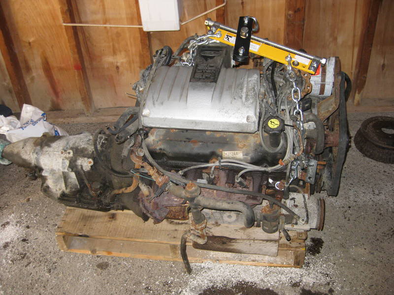
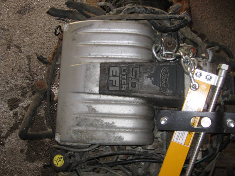
O and the 302 came out of a 86 LTD
O and the 302 came out of a 86 LTD
#58
07-28-2010
Heads/cam/intake would give you a good solid powerplant. Won't get you to 350hp without spending a quite a bit of $$$, but it's a great start. Not sure of all the differences between it and a 5.0L HO but with H/C/I and headers my '94 Mustang was putting out about 325 with a mild tune.
How's the rest of the build going?
How's the rest of the build going?
#60
07-28-2010
#64
07-28-2010
#66
08-20-2010
Join Date: Nov 2008
Location: Oromocto New brunswick
Posts: 791
Likes: 0
Received 0 Likes
on
0 Posts
#67
08-23-2010
Join Date: Nov 2008
Location: Oromocto New brunswick
Posts: 791
Likes: 0
Received 0 Likes
on
0 Posts
Ok, So here are the rest of the pics I had taken during the build.. I work alone, and taking pics isn't my priority. lol..
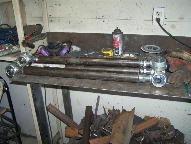
Here are some shots of the material used for the links
Trackbar 1.5" .250 wall of 1026 DOM
Upper Control arm 1.75" .250 wall of 1026 DOM
Lower Control arm 2" .250 wall of 1026 DOM
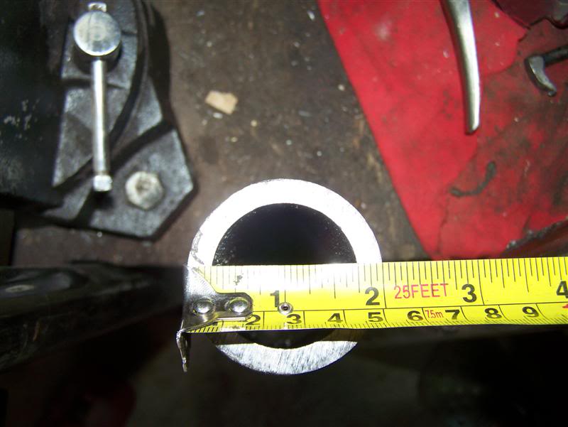
Steering links 1.25" .219 wall of 1026 DOM
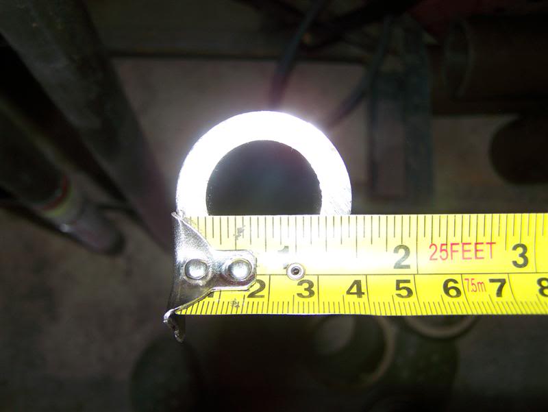
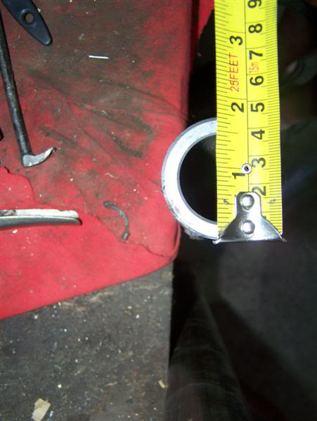
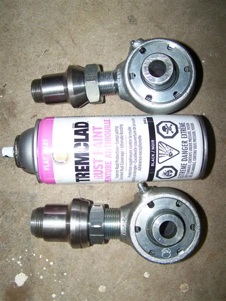
Ballistic joints.. 1" shank upper and 1.25" shank lower both machined out of forged 4140 steel and providing a yield strength of 208,000 psi and a tensile strength of 238,000 psi!
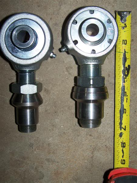
Heres a size comparison.. these things are just Beefy!
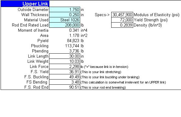
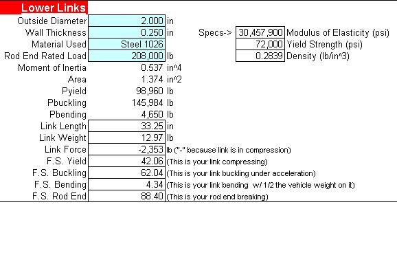
So I knew that with the materials I chose that I was way above the saftey factor of 1 which is what it would take for one of these links to fail. I was using a guide of 1.5 saftey factor. Here are the numbers I came up with for the materials used.
Upper link
Lower Link
I did have the numbers for the 3link, but unfortunatly, I accidentally deleted the damn numbers.. lol.. I'll have to grab them when the truck comes back to get the shackles installed and maybe a swaybar gets put on.
Here are some shots of the material used for the links
Trackbar 1.5" .250 wall of 1026 DOM
Upper Control arm 1.75" .250 wall of 1026 DOM
Lower Control arm 2" .250 wall of 1026 DOM
Steering links 1.25" .219 wall of 1026 DOM
Ballistic joints.. 1" shank upper and 1.25" shank lower both machined out of forged 4140 steel and providing a yield strength of 208,000 psi and a tensile strength of 238,000 psi!
Heres a size comparison.. these things are just Beefy!
So I knew that with the materials I chose that I was way above the saftey factor of 1 which is what it would take for one of these links to fail. I was using a guide of 1.5 saftey factor. Here are the numbers I came up with for the materials used.
Upper link
Lower Link
I did have the numbers for the 3link, but unfortunatly, I accidentally deleted the damn numbers.. lol.. I'll have to grab them when the truck comes back to get the shackles installed and maybe a swaybar gets put on.
#68
08-23-2010
Join Date: Nov 2008
Location: Oromocto New brunswick
Posts: 791
Likes: 0
Received 0 Likes
on
0 Posts
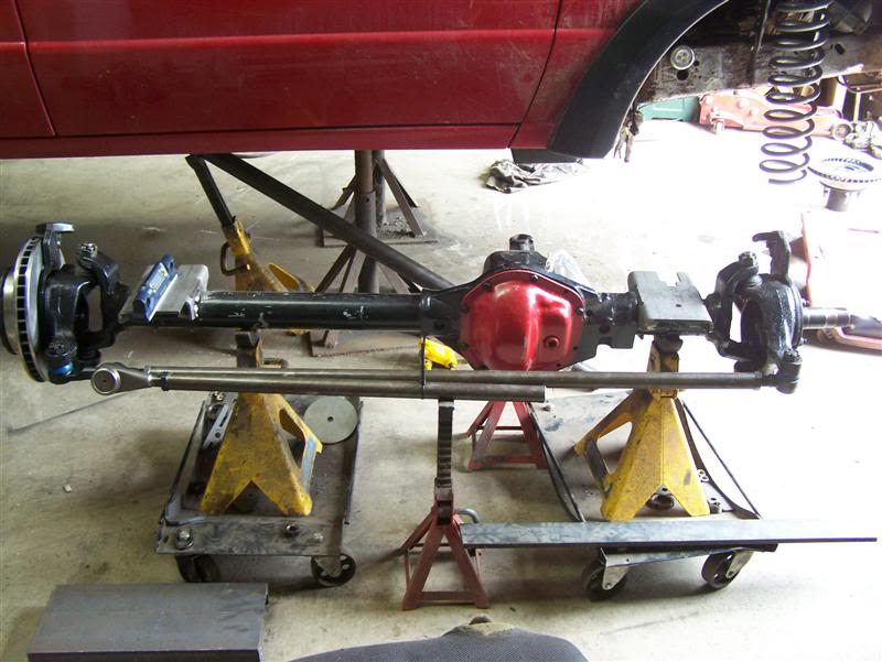
k, Onto some building..
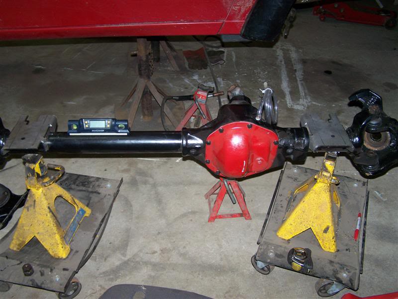
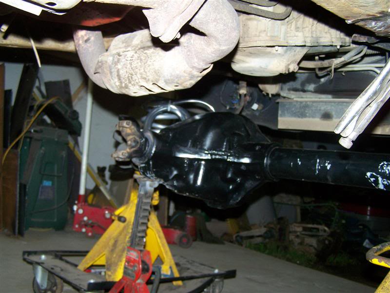
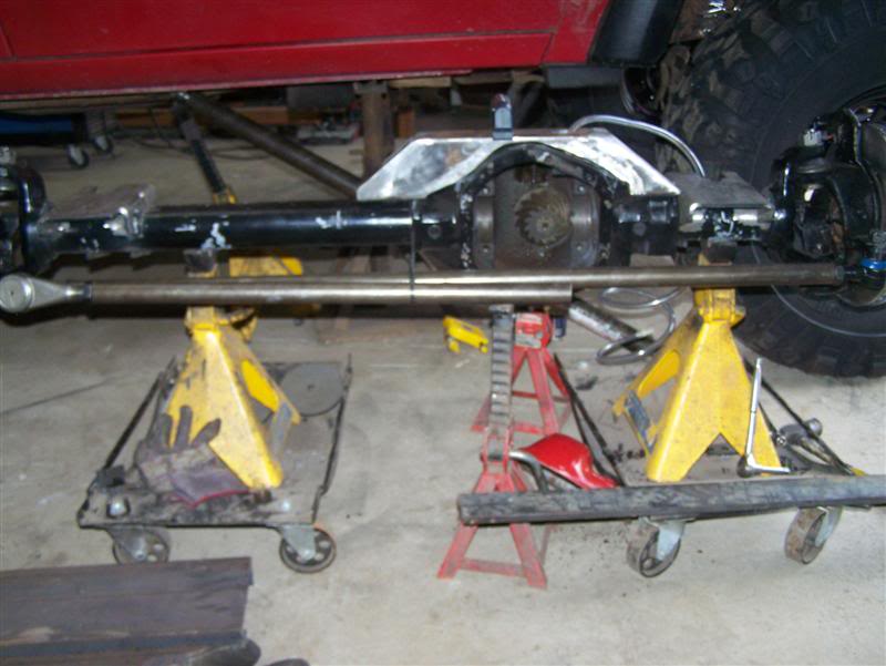
I put the axle on some dollies I had to make it easier to move the axle around
while trying to get things lined up. so I started with finding the caster and
welding the coilbuckets on level. Thought I had a pic of setting caster but apparently I didn't take one. Since I had to replace the upper and lower balljoints on this axle, figured it'd be a great time to measure the caster. I basically took the knuckle off, and used some tapered nuts and some allthread to make a caster tool and used my digital angle finder. I'm not too familiar with rangers but I have always been successful setting caster to 7* + or - 1 on Jeeps. So after some reading I determined to start with 4.5* and can adjust the caster with the adjustable upper control arm later.
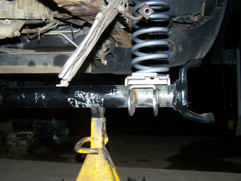
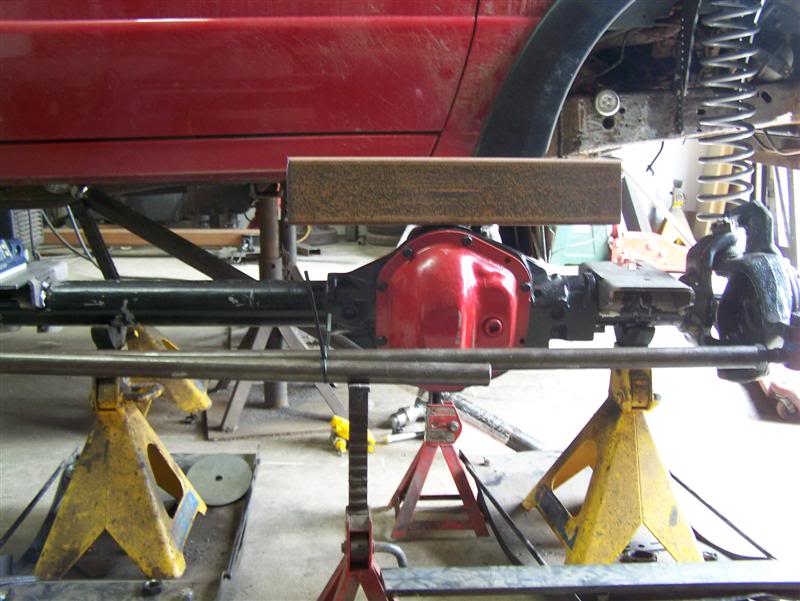
Once I had those welded in, it was time to weld in the Lower control arm mounts.
I wanted to keep them fairly high so they to give better clearance under them..
Then I slid the axle back under the truck for test fitting and get an Idea what
the pinion angle was going to look like.. Bad pic here as the angle looks worse
then what it actually is.
With the axle in place, I put a link together to see where to mount the LCA
frame mount. The Ideal place I wanted to put it was outboard on the frame. but
unfortunatly, I couldn't mount them there without loosing too much turning
radius with the tires rubbing on the arms.. that won't pass inspection. IF it
was just a little I would of gone for it and adjusted the bump stops accordingly
to stop the link from rubbing bit it was too much. WOuld of been nice tho,
tucked away and clean. IF it would of been a wider axle I would of done it.
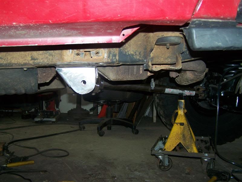
Once I determined the location, I fabbed up a couple frame mounts.
I didn't take a pic, but the stock cross member is still there.. I basically cut
the section that was on the frame and tied these mounts into them. so the mounts
do have lateral support from the inside. there was no real need to fab a new
cross member as the factory one is strong enough and besides, I am going to be
putting in a 302 later and will need a new x-member then(no need to build
something for nothing)..
While I was trying to make up my mind on what to do for an upper mount, I
decided to do the steering. I had done a 1Ton steering upgrade on a XJ JUST
before the Ranger came into the garage and as well as doing quite a few before I
Know it's no easy task tapping about 5" deep in the tube by hand. Basically I
had welded 2 5/8's wrenches together to use as a tap tool.. it actually works
pretty good but gets hard on the hands after a while.. especially after the
taps get a bit dull..
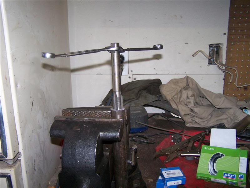
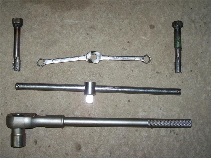
so I opted to upgrade from using that, to getting a bit more grunt! (top is the
before tool.. middle is the starter tool to get the tap straight and the bottom
is the grunt! lol.. as you can see on the taps, I welded 1 1/8" nuts onto them
and now use my 3/4" wrachet drive.. makes life SO much easier.. no more
fighting to keep the tap straight either.
Now, with that done, I mounted the tie rod and draglink to the axle.
Time to get workin on that upper control arm axle mount. So after some hummin
and hawin I wanted to mount the Upper control arm on the passenger side, but the
Rangers have this Gawd aweful exhaust collector Jam goin on over there and it
would be nearly impossible to do so without completly redoing the exhaust.
Thats just too much work and time so I opted to stay away. Maybe after Chris
gets the 302 in, I'll get the truck back for a day to redo the mount on the
passenger side(this would be optimal as it would balance the suspension out a
bit better, but it's not necessary).
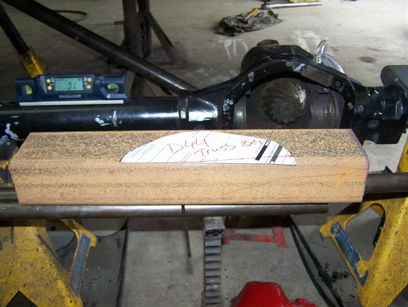
Drivers side it is!! Lets build an axle truss..
Drew up a little template from cardboard
I put the axle on some dollies I had to make it easier to move the axle around
while trying to get things lined up. so I started with finding the caster and
welding the coilbuckets on level. Thought I had a pic of setting caster but apparently I didn't take one. Since I had to replace the upper and lower balljoints on this axle, figured it'd be a great time to measure the caster. I basically took the knuckle off, and used some tapered nuts and some allthread to make a caster tool and used my digital angle finder. I'm not too familiar with rangers but I have always been successful setting caster to 7* + or - 1 on Jeeps. So after some reading I determined to start with 4.5* and can adjust the caster with the adjustable upper control arm later.
Once I had those welded in, it was time to weld in the Lower control arm mounts.
I wanted to keep them fairly high so they to give better clearance under them..
Then I slid the axle back under the truck for test fitting and get an Idea what
the pinion angle was going to look like.. Bad pic here as the angle looks worse
then what it actually is.
With the axle in place, I put a link together to see where to mount the LCA
frame mount. The Ideal place I wanted to put it was outboard on the frame. but
unfortunatly, I couldn't mount them there without loosing too much turning
radius with the tires rubbing on the arms.. that won't pass inspection. IF it
was just a little I would of gone for it and adjusted the bump stops accordingly
to stop the link from rubbing bit it was too much. WOuld of been nice tho,
tucked away and clean. IF it would of been a wider axle I would of done it.
Once I determined the location, I fabbed up a couple frame mounts.
I didn't take a pic, but the stock cross member is still there.. I basically cut
the section that was on the frame and tied these mounts into them. so the mounts
do have lateral support from the inside. there was no real need to fab a new
cross member as the factory one is strong enough and besides, I am going to be
putting in a 302 later and will need a new x-member then(no need to build
something for nothing)..
While I was trying to make up my mind on what to do for an upper mount, I
decided to do the steering. I had done a 1Ton steering upgrade on a XJ JUST
before the Ranger came into the garage and as well as doing quite a few before I
Know it's no easy task tapping about 5" deep in the tube by hand. Basically I
had welded 2 5/8's wrenches together to use as a tap tool.. it actually works
pretty good but gets hard on the hands after a while.. especially after the
taps get a bit dull..
so I opted to upgrade from using that, to getting a bit more grunt! (top is the
before tool.. middle is the starter tool to get the tap straight and the bottom
is the grunt! lol.. as you can see on the taps, I welded 1 1/8" nuts onto them
and now use my 3/4" wrachet drive.. makes life SO much easier.. no more
fighting to keep the tap straight either.
Now, with that done, I mounted the tie rod and draglink to the axle.
Time to get workin on that upper control arm axle mount. So after some hummin
and hawin I wanted to mount the Upper control arm on the passenger side, but the
Rangers have this Gawd aweful exhaust collector Jam goin on over there and it
would be nearly impossible to do so without completly redoing the exhaust.
Thats just too much work and time so I opted to stay away. Maybe after Chris
gets the 302 in, I'll get the truck back for a day to redo the mount on the
passenger side(this would be optimal as it would balance the suspension out a
bit better, but it's not necessary).
Drivers side it is!! Lets build an axle truss..
Drew up a little template from cardboard
#69
08-23-2010
Join Date: Nov 2008
Location: Oromocto New brunswick
Posts: 791
Likes: 0
Received 0 Likes
on
0 Posts
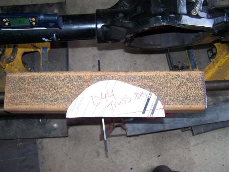
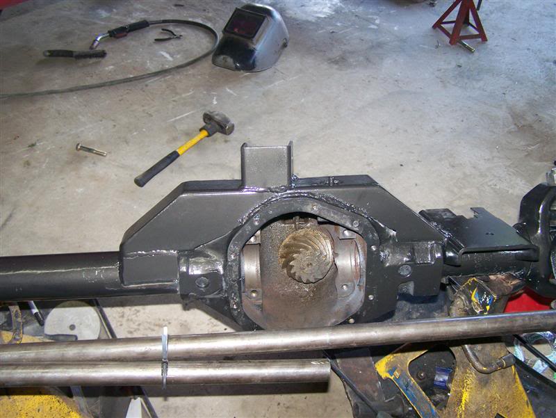
Then it was cut and fit...
Once I liked the fit, I welded it in.. used some 99Ni rods for welding on the
center section. preheated, then wrapped and let cool slowly.
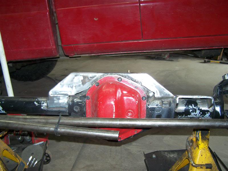
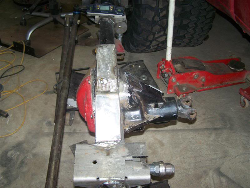
After that was done, I placed the axle back under the truck and jacked it up to
full bump. then placed the uCA bracket on the top of the truss and mounted the
upper arm into it and fit for clearance best I could.. THERE IS NOT ALOT OF
ROOM UNDER THESE DAMN THINGS! lol.. I got it to squeeze JUST between the
exhaust, starter and motor mount(it actually hits the motor mount at full bump
so bump stops are in order)..
#70
08-23-2010
Join Date: Nov 2008
Location: Oromocto New brunswick
Posts: 791
Likes: 0
Received 0 Likes
on
0 Posts
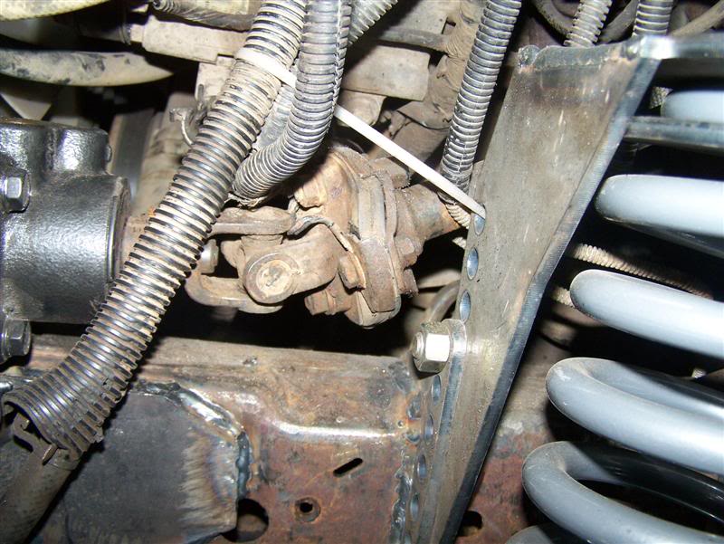
With the axle back in place, it was time to install the steering box. I picked up a Toyota steering box from a 90's 4 runner with IFS. These Boxes seem to be quite easy to work with, easy to find also. They mount on the outside of the frame which makes mounting a bit easier also. Here you see the temp location where I placed it..
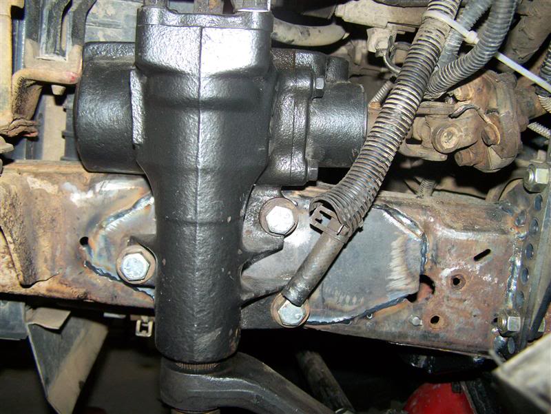
Hind site being 20/20, I should of probably tilted the box upwards a bit to reduce angle on the steering shaft. but it worked well this way also.
So I cleaned up the frame front and back.. To get to the back side, I had to remove the lower rad hose and move a few things around. clean up the frame with the grinder.. I then placed the steering box and marked the location of the holes.. then took out the plasma and cut out 3/4" holes..
Then I used some 1/4" plate to brace the frame.. I used some 3/4" sprinkler pipe I had lyin around and sleeved the holes then welded the plates front and back so I can't crush the frame when torquing down the bolts.
finished product minus the paint of course.
AT this point I had to get the pitman arm in so I could put the drag link in the determine location for the track bar.. So I tried Modding the stock pitman arm. It has a balljoint on the end unlike the Jeep pitman arms. I cut it off thinking I would still be able to use it.. unfortunatly, that was not the case. So I grabbed a XJ pitman arm.. SUrprise, surprise.. the spline on the steering box is much finer then the Jeep boxes.. so I guess I can't use one of those..
2 options, 1 get after market pitman arm(at least a week before I get it), 2 machine a plug with the right taper and weld it in the toy pitman arm.. This was the route I was going to take I was looking for some solid stock to machine(read grinder here to fit the OD and ream with proper reamer) when Eric(Redyotarunner on the NBoffroad board) Dropped in. He's buildin a 4Runner but isn't quite done yet. As we were chattin away I explained my dilema and he offered me to use his TRailgear pitman arm he was using with his high steer kit. i can pay him for it or replace it.. THis way at least I didn't have to wait a week to get it in. THanks Alot ERIC!
So I took a shot over to his place and picked up the pitman arm, reamed it out for the Chev 1Ton Tres and was good to go..
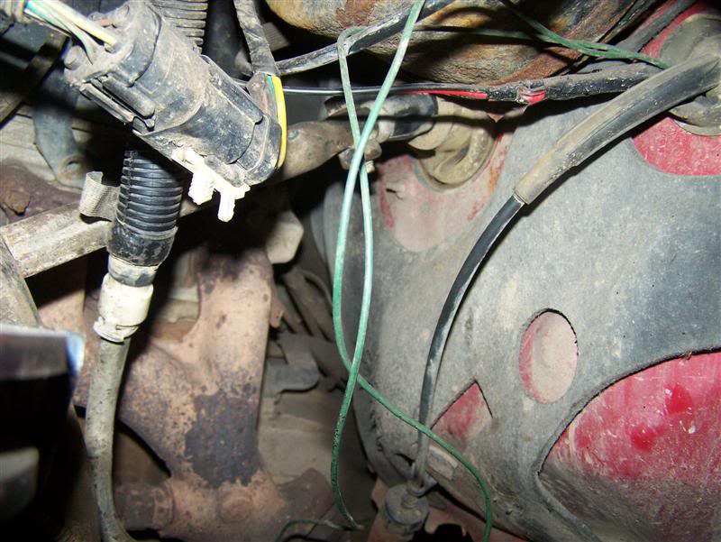
With that in place, next step was to take the 2 steering shafts and make 1 out of them.. Yota shaft top, Ranger shaft bottom.
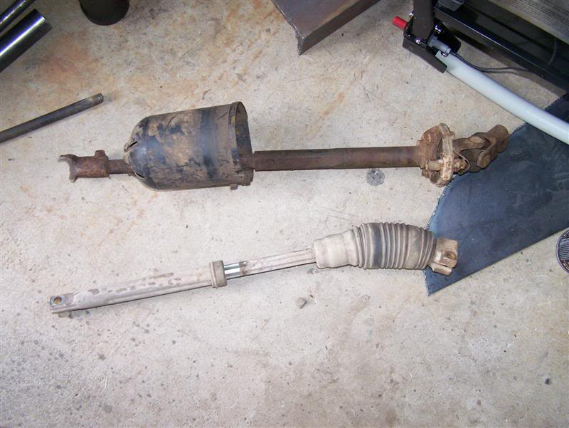
what I did was on the yota shaft, I pounded out the sliding peice. Then cut the main peice with the knuckle down a bit shorter. then on the ranger shaft, I cut the knuckle out and left about 1" of the "flange". I machined the flange to fit inside the yota shaft I had cut down. THis worked like an indexing ring like a driveshaft to line up the shaft straight and welded it in. So I still have the saftey compression(read slip) of the shaft in case of front end impact. worked out pretty good. (sorry for lack of picks on this one was just workin away in the "zone" and forgot to take some.. lol)
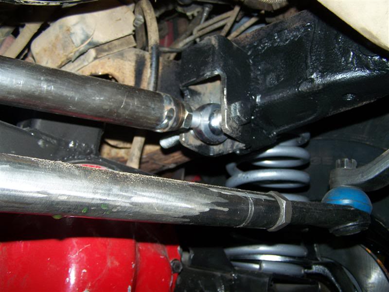
Here you see it mounted. tight squeeze, but it fits withouth interfearance.
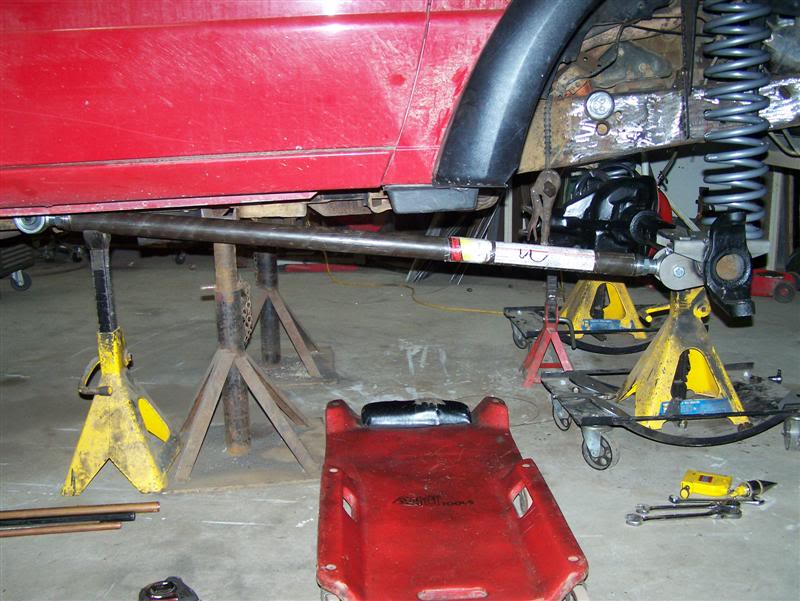
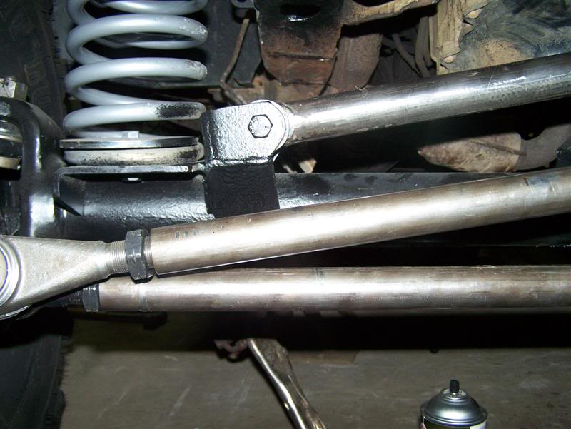
Once that was done, I installed the drag link and mounted the trackbar.. Looks a little off here but it's parallel
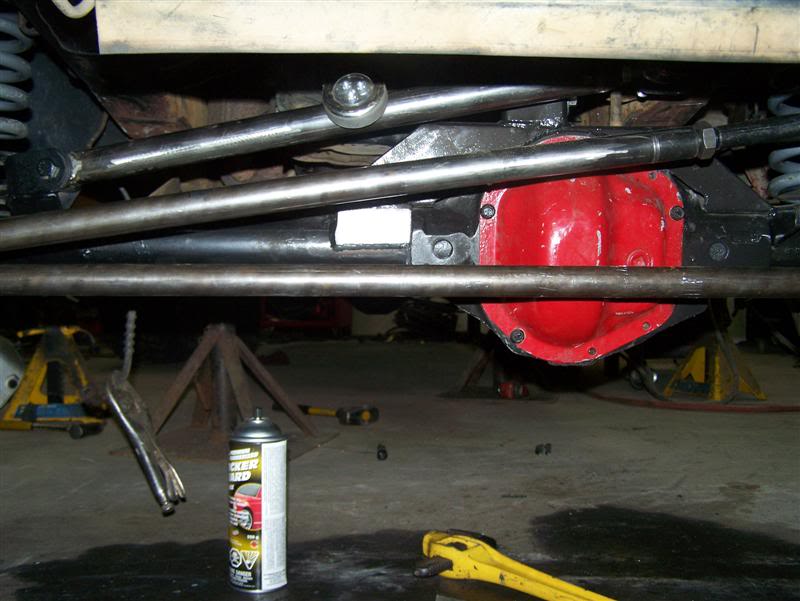
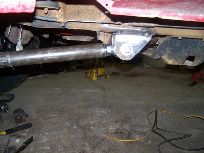
axle Mount for trackbar/panhard bar
frame mount for trackbar/panhard bar
Heres a shot of the arms when sitting at ride height. the upper is pretty much parallel to the ground with 9" separation from the lowers.
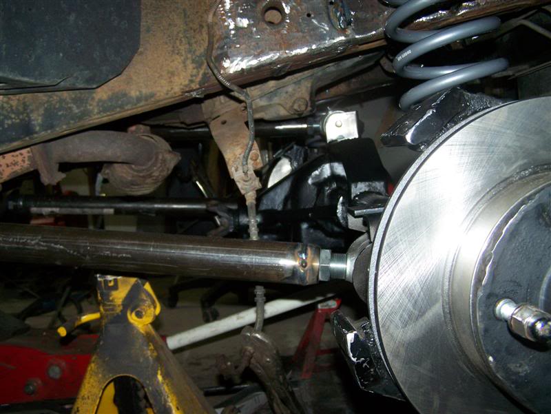
Time to install calipers, brake lines, rebuild the hubs, install lockouts, all the little tidious stuff.
Speaking of shocks, had some 14" travel shocks to use, but due to lack of space on the ranger, couldn't install them. needed to figure out a location to put them and allow good travel without causing any stability issues.. This is what I came up with..
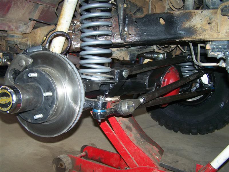
Not optimal, I know, but works pretty good. doesn't interfear with anything else and once he lifts the rear a bit more and adjusts the coil buckets for more height, he can relocate the shocks if there is enough room then..
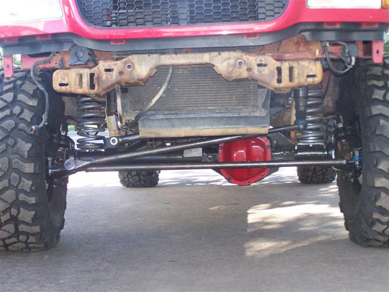
couple finished shots...
Hind site being 20/20, I should of probably tilted the box upwards a bit to reduce angle on the steering shaft. but it worked well this way also.
So I cleaned up the frame front and back.. To get to the back side, I had to remove the lower rad hose and move a few things around. clean up the frame with the grinder.. I then placed the steering box and marked the location of the holes.. then took out the plasma and cut out 3/4" holes..
Then I used some 1/4" plate to brace the frame.. I used some 3/4" sprinkler pipe I had lyin around and sleeved the holes then welded the plates front and back so I can't crush the frame when torquing down the bolts.
finished product minus the paint of course.
AT this point I had to get the pitman arm in so I could put the drag link in the determine location for the track bar.. So I tried Modding the stock pitman arm. It has a balljoint on the end unlike the Jeep pitman arms. I cut it off thinking I would still be able to use it.. unfortunatly, that was not the case. So I grabbed a XJ pitman arm.. SUrprise, surprise.. the spline on the steering box is much finer then the Jeep boxes.. so I guess I can't use one of those..
2 options, 1 get after market pitman arm(at least a week before I get it), 2 machine a plug with the right taper and weld it in the toy pitman arm.. This was the route I was going to take I was looking for some solid stock to machine(read grinder here to fit the OD and ream with proper reamer) when Eric(Redyotarunner on the NBoffroad board) Dropped in. He's buildin a 4Runner but isn't quite done yet. As we were chattin away I explained my dilema and he offered me to use his TRailgear pitman arm he was using with his high steer kit. i can pay him for it or replace it.. THis way at least I didn't have to wait a week to get it in. THanks Alot ERIC!
So I took a shot over to his place and picked up the pitman arm, reamed it out for the Chev 1Ton Tres and was good to go..
With that in place, next step was to take the 2 steering shafts and make 1 out of them.. Yota shaft top, Ranger shaft bottom.
what I did was on the yota shaft, I pounded out the sliding peice. Then cut the main peice with the knuckle down a bit shorter. then on the ranger shaft, I cut the knuckle out and left about 1" of the "flange". I machined the flange to fit inside the yota shaft I had cut down. THis worked like an indexing ring like a driveshaft to line up the shaft straight and welded it in. So I still have the saftey compression(read slip) of the shaft in case of front end impact. worked out pretty good. (sorry for lack of picks on this one was just workin away in the "zone" and forgot to take some.. lol)
Here you see it mounted. tight squeeze, but it fits withouth interfearance.
Once that was done, I installed the drag link and mounted the trackbar.. Looks a little off here but it's parallel
axle Mount for trackbar/panhard bar
frame mount for trackbar/panhard bar
Heres a shot of the arms when sitting at ride height. the upper is pretty much parallel to the ground with 9" separation from the lowers.
Time to install calipers, brake lines, rebuild the hubs, install lockouts, all the little tidious stuff.
Speaking of shocks, had some 14" travel shocks to use, but due to lack of space on the ranger, couldn't install them. needed to figure out a location to put them and allow good travel without causing any stability issues.. This is what I came up with..
Not optimal, I know, but works pretty good. doesn't interfear with anything else and once he lifts the rear a bit more and adjusts the coil buckets for more height, he can relocate the shocks if there is enough room then..
couple finished shots...
#71
08-23-2010
Join Date: Nov 2008
Location: Oromocto New brunswick
Posts: 791
Likes: 0
Received 0 Likes
on
0 Posts
And that is it for now. I am starting to piece together my 4 link for the rear. A buddy of mine said that he will give me a 8.8 rear out of a 96 F150 for $50 buck. Which is awesome because then I will be able to swap my gears and everything over in to that rear end. I think At the same time I am going to Box in the rear and Bed liner the frame.
But I am not sure what I should run for coils in the rear. Does anyone have suggestions. I am still going to be hauling my snowmobile trailer with it this winter so keep that in mind.
But I am not sure what I should run for coils in the rear. Does anyone have suggestions. I am still going to be hauling my snowmobile trailer with it this winter so keep that in mind.
#74
08-23-2010
Join Date: Nov 2008
Location: Oromocto New brunswick
Posts: 791
Likes: 0
Received 0 Likes
on
0 Posts
Ya it is pretty kick a$$. The only thing is tho is that there is only like 3 inches between my upper link and my motor mount. And every bump I hit i bottom out. I need to lift the front more and go from there.
#75
08-23-2010
Join Date: Nov 2008
Location: Oromocto New brunswick
Posts: 791
Likes: 0
Received 0 Likes
on
0 Posts
O trust me she rubs. lol. She rubs more then a cheap hooker on pay night. I still need to lift it a bit more once I get some more blocks for the back. I know I know blocks are gross but they will have to do until I get the 4 link in there. Hopefully I will have that done before Christmas.


