Wiring Diagram Confusion
#1
 11-10-2016


Wiring Diagram Confusion
Hopefully someone knows how to decipher this particular diagram.
I've read several of these diagrams, all very similar in form factor, but this one is throwing me for a bit of a curve.
First off, I bet a bit of context may help. I have a double throw momentary switch, one side which isn't being used. A member in my build log suggested to use the switch as a means of something like a kill switch, where the key must be turned forward, and the switch activated for the starter to work.
Awesome idea, which I may or may not incorporate later in a bit of a different place. So, instead, I'm opting to take this idea and spin it a bit.
I'm wanting to make the switch act as another way to activate the starter. IE, turn the key to 'on', flip the switch and she starts up. I plan to have this wired in parallel so the key can still start the truck, if something goes wrong so I'm not stranded.
Now that my plans are known, I'm trying to figure out what this diagram is telling me. Mine is the automatic tarnsmission.
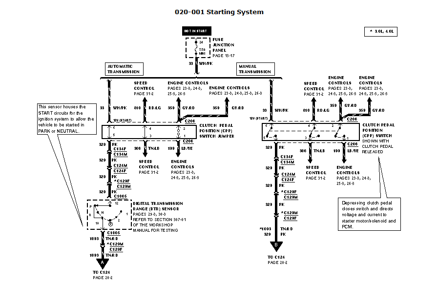
There's the DTR switch as expected, with a small '12' inside the DTR 'box', seemingly marking this area as +12 hot. Move up a little further and we see a white with pink wire and a -12V symbol near the CPP switch jumper, at pins 6 and 5. Above this we see there's a 'hot in start' bus.
The hot in start would tell me the white and pink wire is hot, and therefor must be pulled to ground, but the -12V tells me it should be pulled to power.
Any ideas? I'd rather not burn something up if I can avoid it.
I've read several of these diagrams, all very similar in form factor, but this one is throwing me for a bit of a curve.
First off, I bet a bit of context may help. I have a double throw momentary switch, one side which isn't being used. A member in my build log suggested to use the switch as a means of something like a kill switch, where the key must be turned forward, and the switch activated for the starter to work.
Awesome idea, which I may or may not incorporate later in a bit of a different place. So, instead, I'm opting to take this idea and spin it a bit.
I'm wanting to make the switch act as another way to activate the starter. IE, turn the key to 'on', flip the switch and she starts up. I plan to have this wired in parallel so the key can still start the truck, if something goes wrong so I'm not stranded.
Now that my plans are known, I'm trying to figure out what this diagram is telling me. Mine is the automatic tarnsmission.
There's the DTR switch as expected, with a small '12' inside the DTR 'box', seemingly marking this area as +12 hot. Move up a little further and we see a white with pink wire and a -12V symbol near the CPP switch jumper, at pins 6 and 5. Above this we see there's a 'hot in start' bus.
The hot in start would tell me the white and pink wire is hot, and therefor must be pulled to ground, but the -12V tells me it should be pulled to power.
Any ideas? I'd rather not burn something up if I can avoid it.
#2
11-10-2016


Where is the diagram?
If you want a START button then you simply run KEY ON 12volts to the switch and then a wire from the switch to the Starter Relay, you don't need to touch the Key start system.
KEY ON power is in the cab fuse panel
KEY ON power means START button only works with KEY ON
Starter Relay can be on the inner fender, engine fuse box or on the starter motor itself depending on the year and engine
This would by-pass the NSS(neutral safety switch) on the automatic trans.
#3
11-10-2016
Whoops, sorry. That's what I get for multitasking, lol.
I may go that route instead, however, I would like to keep the NSS in play, even though I only start it in park, except for that rare occasion in neutral.
If I did wind up going that route, I would definately use key hot power, though, so something couldn't fall on the switch while I'm away (say a drink or something) activate the switch and both kill the starter and possibly battery, too.
Although I do like the advantage of not having to dork around with the stock harness.
#4
11-10-2016
Then yes, according to that diagram all you need to do is splice into the Pink wire coming out of the Clutch switch "Jumper" connector, or the white/pink, your choice
Send that spliced wire 12volts and starter will activate if trans is in Park or Neutral
If you used Key ON power then it would only work if key is on
Send that spliced wire 12volts and starter will activate if trans is in Park or Neutral
If you used Key ON power then it would only work if key is on
#5
11-10-2016
#6
11-10-2016
Not sure '99 Rangers had the starter relay cut off with PATS.
Wouldn't matter in any case for what you are doing.
The PATS starter cut off was the computer Grounding the Starter Relay if the key passed the PATS test.
If relay is not Grounded then sending it 12volts will not close it so no starter motor.
The first PATS units in Rangers just had fuel injection and fuel pump "no grounds" if PATS test failed, the no ground for starter relay was added later.
#7
11-11-2016
Yes, I do have PATS. I had wound up taking one of my old, breaking up keys and took the actual key portion out, leaving the plastic behind for an emergency key I could place in my wallet.
Of course I had to try it, and as I expected, no starter without the PATS chip. Hopefully that won't cause an issue if the key is in the ignition. I wouldn't think so. We'll find out today here after a while.
Of course I had to try it, and as I expected, no starter without the PATS chip. Hopefully that won't cause an issue if the key is in the ignition. I wouldn't think so. We'll find out today here after a while.
#8
11-11-2016
Took a little longer than I expected.
I wound up finding the CPP jumper (since mine is auto) and sent 12+ into the solid pink wire. Oddly enough, the white with pink wire is nowhere to be found, not even in the CPP jumper. Not sure why that is.
I had an existing 'key hot' add-a-circuit so I pulled the current from that, upgrading the fuse of course to 7.5 amps from 5, wired in the switch and now I can start it with a momentary switch instead of turning the ignition barrel.
Not exactly sure why I wanted to, but it costs me nothing so, why not?
#9
11-11-2016
#10
11-11-2016

Thread
Thread Starter
Forum
Replies
Last Post
Alucard
General Technical & Electrical
24
11-19-2005 02:23 PM
Chodemnky
General Technical & Electrical
4
04-29-2005 02:30 PM


