Stuff around the shop.
#1
 09-23-2009


Stuff around the shop.
Figured I'd make a thread to keep updating with some pictures of **** I build around the shop. Since I never have time to work on the ranger I'll take some pictures of the stuff I actually am working on.
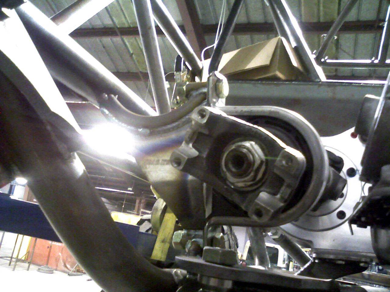
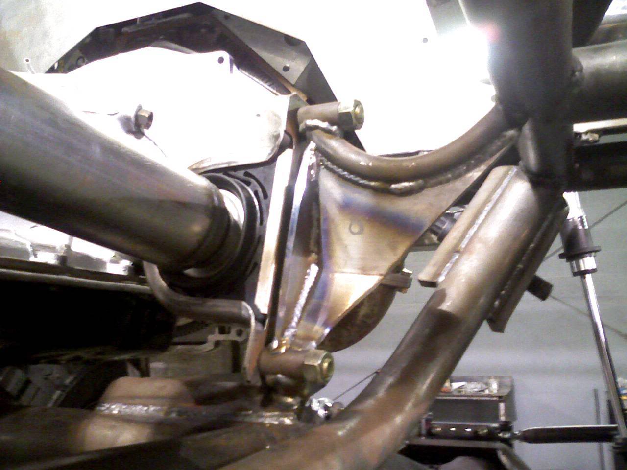
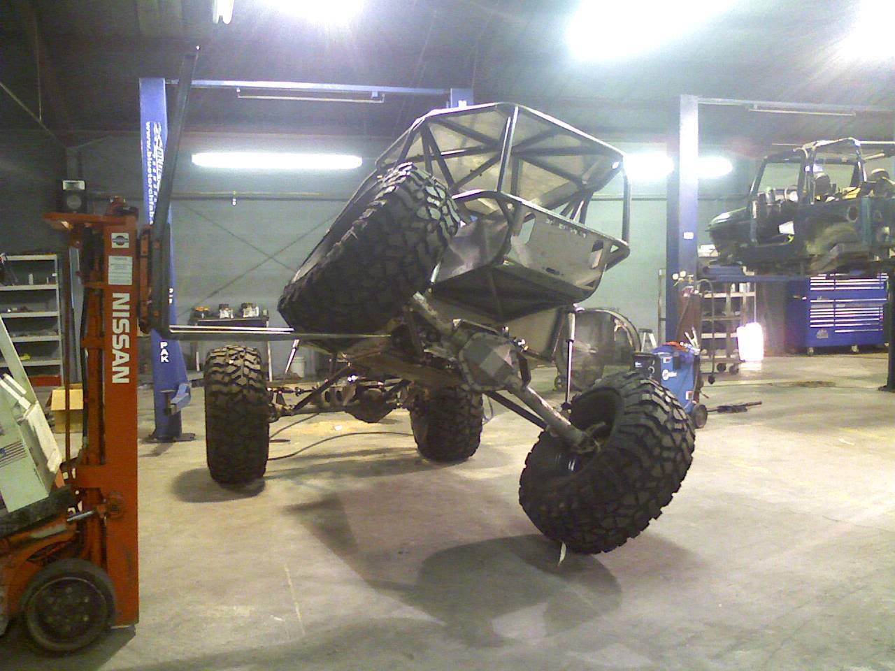
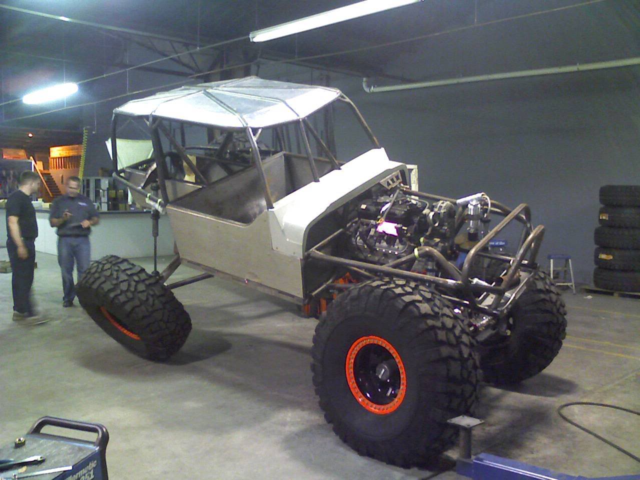
This is a carrier bearing mount on a fusion chassis I'm finishing up.
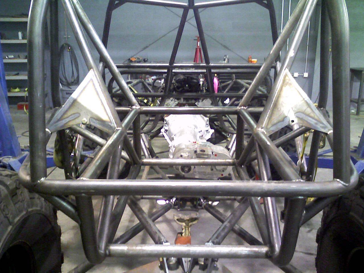
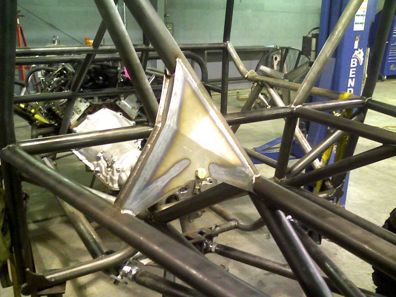
Rear shock mounts from same build.
This is a carrier bearing mount on a fusion chassis I'm finishing up.
Rear shock mounts from same build.
#2
09-23-2009
#5
09-23-2009
Is this a common thing for buggies?
#6
09-23-2009


#7
09-23-2009
#10
09-24-2009
Ok... so the 2nd section of Driveshaft uses a slip joint? And if so, isn't that harder on the U-Joints due to the fact at full droop your angle to the front case will be pretty steep?

#14
09-30-2009

#16
09-30-2009
#18
09-30-2009
Originally Posted by 99ranger4x4
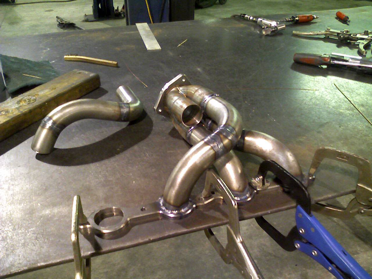
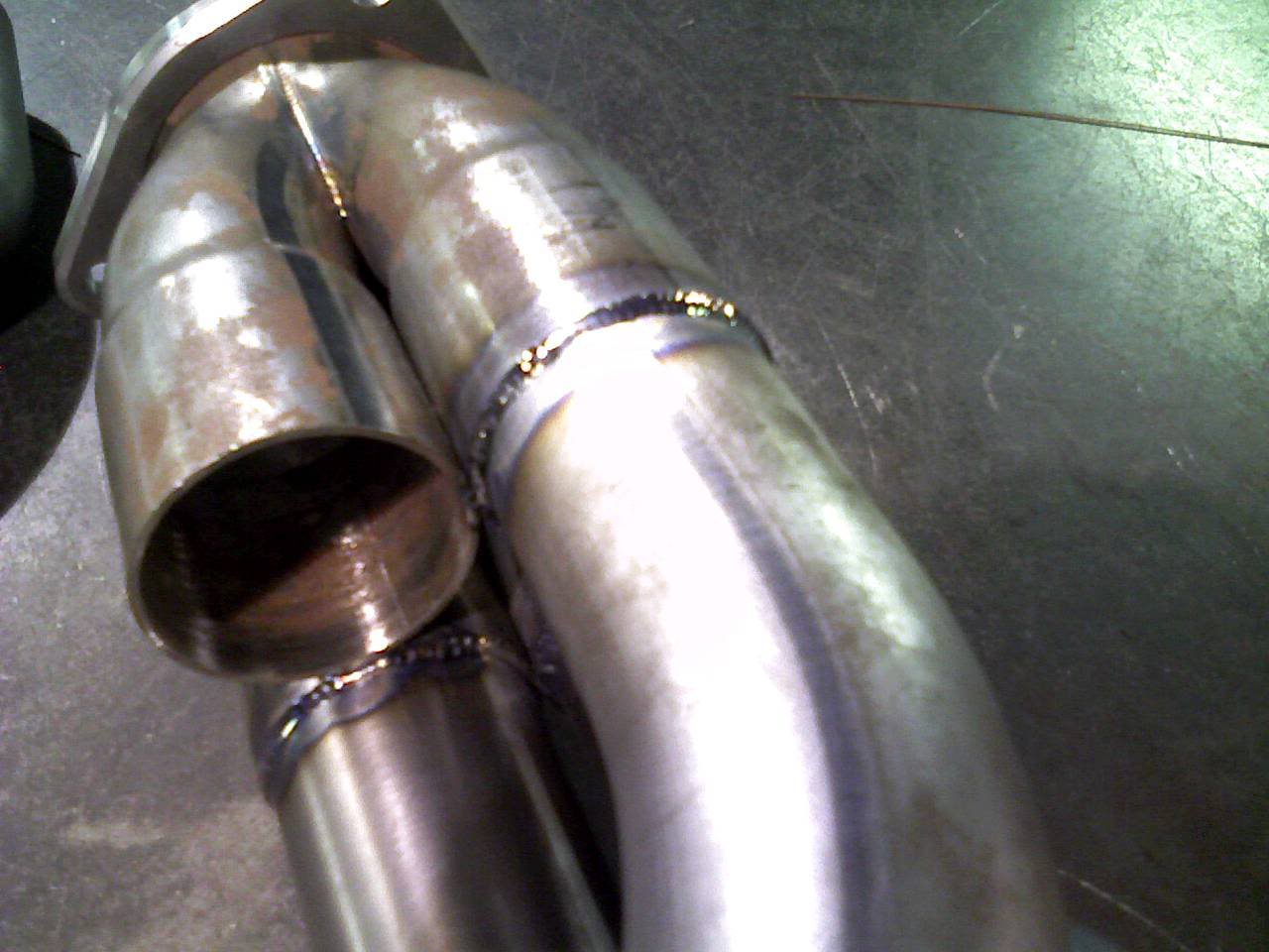
how the hell are you welding in such tight spaces?
#21
09-30-2009
#22
09-30-2009
#23
09-30-2009
no i know how you get it fit up. but how do you get the middle of the last pipe welded where it connects to the collector?
#24
10-01-2009
I usually mount the bolts front to back so that while articulating the rod ends don't move, except for the front to back (arc) movement of the axle.
You don't. The tubes are a tight slip fit and you just weld as much as you can. If there is a chance for a leak, the ceramic coating takes care of it.


