
Adding cruise control to a non-prewired truck

Joined: Aug 2007
Posts: 5,809
Likes: 4
From: Indiana/Mississippi

Adding cruise control to a non-prewired truck
Went to the yard today and got the servo for my truck and the entire steering column with buttons. Is there anything else I need? Looked around and looked like something about a master cylinder? Where would I go to find a wiring diaghram for my '99? I need to find which wire is for the light in the dash and what all the wires are on the servo.
Thanks for the help.
Thanks for the help.
Member
Joined: Apr 2010
Posts: 645
Likes: 2
From: Knoxville, TN

Did you get the cable? The cable is specific for engines. also get the connector that goes to the servo. I would also get the plug that goes to your clock spring wiring. Its the same as yours but has like 2 extra wires for the buttons. Pretty much it would be for "repinning" your current plug so that you can easily disconnect the harness to remove the column if you ever have to.
Don't worry about the master cylinder. The sensor on it is just a backup for if your brake light switch doesn't work. There was a recall on this switch that caused fires. You can jump the wire that is suppose to go to the sensor to a 12 volt source and it acts like it is always there.
I'll get you some diagrams tomorrow.
Joined: Aug 2007
Posts: 5,809
Likes: 4
From: Indiana/Mississippi
Awesome! Appreciate it. I got the servo and the cable that goes to my motor. Already have it on the truck. As for the wiring for the column, where it connects to the truck I cut them off on the truck side and got as much extra wire on the other side as I could get. Also did the same with the wiring for the servo plug.

Member
Joined: Apr 2010
Posts: 645
Likes: 2
From: Knoxville, TN


The top picture shows the steering column wiring. The only thing you need to worry about is the red highlighted wires. These are in that brown 6 pin connector. To add pins to the connector on the truck side, there should be a red plug and when you remove that you can remove the pins (after you move a little tab, should be able to see this).
The black/yellow wire can be jumped to the Grey/Yellow wire. As long as the black/yellow wire has 12v, the servo thinks that the pressure switch is there and the brakes aren't applied. But you do have the actual brake switch on the pedals to turn off the cruise.
BTW on a Ranger for your year your cruise control buttons most likely won't light up. Your steering column wiring is wired for this, but it is the truck side that isn't. You can add an extra pin on the truck side to match the LB/RD wire on the column side.
Joined: Aug 2007
Posts: 5,809
Likes: 4
From: Indiana/Mississippi
AWESOME! I appreciate you posting those. I'm gonna first get the column swapped in then work on the wiring later. Ya, I saw about adding a wire to make the pods light up.
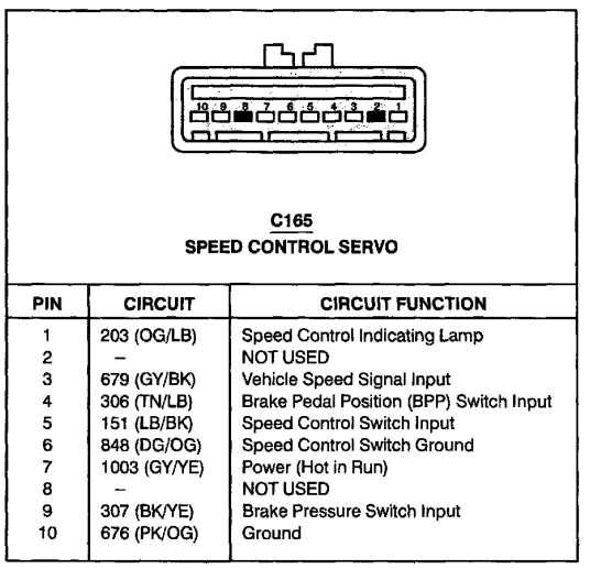
So are there only two wires that I need to hook up for the steering column? One looks to be a speed control ground which goes to two spots on the servo? The other one looks like C165 which gets an all the time hot but gets interrupted by the brake when pushed. What do I need for making that work? Looks like there is also something for the clutch switch?
On the servo, what is the speed control input? It says to look at diagram 31-1. Do you happen to have that and diagram 31-2?
I guess not I need to figure out how to swap the ignition cylinders.
Member
Joined: Apr 2010
Posts: 645
Likes: 2
From: Knoxville, TN
AWESOME! I appreciate you posting those. I'm gonna first get the column swapped in then work on the wiring later. Ya, I saw about adding a wire to make the pods light up.
So are there only two wires that I need to hook up for the steering column? One looks to be a speed control ground which goes to two spots on the servo? The other one looks like C165 which gets an all the time hot but gets interrupted by the brake when pushed. What do I need for making that work? Looks like there is also something for the clutch switch?
On the servo, what is the speed control input? It says to look at diagram 31-1. Do you happen to have that and diagram 31-2?
I guess not I need to figure out how to swap the ignition cylinders.
The wire that needs to be hot at all times can just be jumped to the ignition power wire as I said before.
The clutch switch is inline with the brake switch. If you have an automatic you just have a jumper there instead of a switch. So this means if you press in the clutch or tap the brake that circuit will be broken.
Screwdriver/chisel and hammer for the ignition switch. Just keep chiseling away the guts till you can get it out. What I did.
Joined: Aug 2007
Posts: 5,809
Likes: 4
From: Indiana/Mississippi
Oh I see. Well like on A on the top picture says it goes to C135 and on the second picture for A it says to C219.
So for the clutch and brake switch, what do I need to get for it? In the picture they have something to stop the flow of current when the clutch or brake is depressed. I have a manual trans.
So for the clutch and brake switch, what do I need to get for it? In the picture they have something to stop the flow of current when the clutch or brake is depressed. I have a manual trans.
Member
Joined: Apr 2010
Posts: 645
Likes: 2
From: Knoxville, TN
Connect they tn/lb wire from the cruise servo to the tn/lb coming from your clutch switch (near pedal).
It says its coming form C219 (brown 6 wire plug on bottom of column).
C135 is the big 3 bulk head connectors that go through the firewall (behind fuse box under hood).
It says its coming form C219 (brown 6 wire plug on bottom of column).
C135 is the big 3 bulk head connectors that go through the firewall (behind fuse box under hood).


Thread
Thread Starter
Forum
Replies
Last Post
95Rangerjunkie
DOHC - 2.3L Duratec / Mazda L Engines
4
Aug 21, 2009 03:22 PM
2001fordranger
General Technical & Electrical
1
Jul 29, 2009 10:58 PM


