
Instrument cluster test mode


Instrument cluster test mode
I knew Mustangs could do it, but i was waiting today in a parking lot and tried it out on the Ranger. Hey it works!
Its just kind of a cool thing to play with. Shows a digital tach, volts and a bunch of other diagnostic things. Anyone else ever mess with it?
Its just kind of a cool thing to play with. Shows a digital tach, volts and a bunch of other diagnostic things. Anyone else ever mess with it?
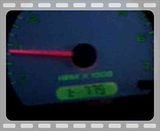
With the key off, hold down the trip reset button. Turn the car on and then let go of the button. I think it starts on the "gauges" setting first, so youll see the needle sweep (like in the vid) and each time you press the trip button youll hit a different screen. Lots are diagnostic things that i dont know the codes for, but the digital tach is cool, the digital volt meter and some other stuff. Seeing all of the warning lights on at once is cool too.
AFAIK, it works on the models with the digital odometers. Mustangs work from 99-04 at least. My mom has an 02, thats where i remember it from lol.
never mind i googled it it says QUOTE (i didnt write this i copy and pasted dont sue me )
To access Engineering Mode put your key into the ignition press down the reset button by the message center/odometer and turn the key to the on position, continue holding it and you should see ENGINEERING MODE pop up on the screen. Let go of the reset button. Simply push the reset button to scroll through all of the different readouts! You may get the CHECK CHARGING SYSTEM warning, just press the reset button to keep looking.
To access Engineering Mode put your key into the ignition press down the reset button by the message center/odometer and turn the key to the on position, continue holding it and you should see ENGINEERING MODE pop up on the screen. Let go of the reset button. Simply push the reset button to scroll through all of the different readouts! You may get the CHECK CHARGING SYSTEM warning, just press the reset button to keep looking.


should only be on 2004+ i would assume
On the instrument cluster press and hold the RESET button, turn the ignition switch to the ignion on position II, and then continue pressing the RESET button (5 seconds) until test is displayed in the odometer. The SELECT/RESET button must be released within three seconds of the odometer test display to begin the dealer test mode. Depress the SELECT/RESET button to advance through the following steps until dtc is displayed. Depressing the SELECT/RESET button will display any stored continuous DTCs before proceeding to the next step. Odometer Display Description GAGE= Activates gauge sweep of all gauges, then displays present gauge values. Also carries out the checksum tests on ROM and EE. If the gauge sweep is inoperative, INSTALL a new instrument cluster. All segments illuminated Illuminates all odometer segments. If any odometer segment is inoperative INSTALL a new instrument cluster. BLUB= Illuminates all micro-controlled indicators and LEDs. Install a new indicator or LED as necessary. R= Returns to normal operation of all micro-controlled indicators and LEDs and displays hexadecimal value for ROM level. If alternating flashes for FAIL and ROM level are displayed, INSTALL a new instrument cluster. EE= Displays the hexadecimal value for EE level . If alternating flashes of FAIL and EE level are displayed replace instrument cluster. DT= Displays hexadecimal coding of final manufacturing test date . DTC = Displays continuous DTC's in hexadecimal format. Pressing the SELECT/RESET button will display any DTCs stored before proceeding to the next step. See index below for description of trouble codes. ENG= Displays the English speed in MPH. Speedometer will indicate present speed within tolerances. Display will show 0 if input in not received. If input is invalid for one second or more, or if speed is 0. M= Displays the metric speed data in kph. Speedometer will indicate present
speed within tolerances. Display will show 0 if input in not received. If input is invalid for one second or more, or if speed is 0. TAC= Displays the tachometer data received from the PCM via the SCP network within tolerances. Tachometer will indicate present RPM. Display will show 0 if input is no received, if input received is invalid for one second or more, or if engine RPM is 0. FUEL= Displays the code (0-255) for the fuel sender input to the HEC. The fuel gauge will display a filtered fuel level value. This filter will keep the pointer from moving suddenly or erratically. 255= open send +/- 0 232= full stop +/- 0 215= Full mark +/- 10 178= 3/4 mark +/- 8 138= 1/2 mark +/- 7 93= 1/4 mark +/- 5 41= E mark +/- 4 54= Low Fuel (0-59) 0-18= short (0-20 max) OIL= Displays the code (0-250) for the oil pressure switch input to the HEC. Oil pressure gauge will indicate present oil pressure. Normal oil pressure (greater than 6psi) will display a value between 000 and 176. A low oil pressure or an inoperative engine oil pressure switch (less than 6 psi) will display a value greater than 176. dEG'C= Display of engine temperature in Degrees C input from cylinder head temperature sensor. 49 C= "C" mark 60 C= Normal band start 120 C= Normal band end -40 C= No SCP message for 5 seconds battery voltage Displays the code (0-255) for the battery voltage input to the HEC. Battery voltage gauge will indicate present battery voltage. 93-102 6.2-9.1 volts, low voltage 115-124= 8.5-10.7 volts, Normal band star t 215-225= 15.8-18 volts, Norm band end 230-241= 16.9-19.1 volts, high voltage rhEo= Displays the present decimal rheostat dimming input, 0-255 rhi rhS
rho Not used. CR= Displays the current RUN/START sense input. Display will show -h for high input with the ignition switch in the START position and -L for low input with the ignition switch in the RUN position. PA-PE7= not used. GAGE= Repeats the display cycle To exit the HEC Dealer Test Mode, turn the ignition switch to the OFF position ------------------------------------------------------------------------ NOTE: DTC Codes are not to be used for diagnosing problems. If you believe there is a problem with your car, you should have it scanned with an code reader. DTC Description Common Diagnostic Trouble Codes B1202 9202 Fuel Sender Open Circuit B1204 9204 Fuel Sender Short to Ground B1213 9213 Anti-Theft Number of Programmed Keys is Below Minimum B2103 9232 Antenna Not Connected - Defective Transceiver B1232 A103 Antenna Not Connected - Defective Transceiver B1317 9317 Battery Voltage High B1318 9318 Battery Voltage Low B1342 9342 ECU Is Defective B1356 9356 Ignition Run Circuit Open B1364 9364 Ignition Start Circuit Open B1600 9600 PATS Ignition Key Transponder Signal is Not Received - Damaged Key or Non -PATS Key B1601 9601 PATS Received Incorrect Key-Code from Ignition Key Transponder (Unprogrammed Key) B1602 9602 PATS Received Invalid Format of Key-Code From Ignition Key Transponder (Partial Key Read) B1681 9681 PATS Transceiver Signal is Not Received (Not Connected, Damaged, or Wiring) B2139 A139 PCM ID Does Not Match Between Instrument Cluster and PCM B2141 A141 NVM Configuration Failure (No PCM ID Exchange Between Instrument Cluster and PCM) B2143 A143 NVM Memory Failure C1284 5284 Oil Pressure Switch Failure


Member
Joined: Mar 2018
Posts: 5
Likes: 0
From: Edmonton, AB
Start with the key in the off position. Hold the trip button for a second or two and, while still holding the button, turn the key to the on position (you do not have to start the engine). Release the button when "tEst" is displayed on the odometer. Push the button again to cycle through the options.

Thread
Thread Starter
Forum
Replies
Last Post
ShadowRanger
General Technical & Electrical
15
Jul 13, 2006 10:13 PM


