To those who have installed alarms.. Help Idiot
#1
 09-01-2009


Alright,
Not too educated on these systems of alarms/key less/relays..etc, but I'm making it a learning opportunity, so please help educate me :)
Yesterday I Installed DEI actuators in both my doors, routed the wires through the door boot and under the dash on the driver side. I tested with 9V battery, and both are working well. They are the two wired actuators so I have one blue and one green running from each door.
From what I have gathered, the next step is relays, I found black99's how to, and the diagram :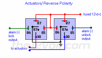
-- Is this right?
If I get the green light, I'll start working on that next. My big concern is the install of the alarm. I ordered one last night, I got a good deal ( I feel ) on a new autopage 525 @ $90 after shipping. (life warentee)
I have been looking around at the12volt.com and trying to do some reading here, but the unclear threads I have researched have made me skeptical on my abilities.
From the 12volt :
NOTE: This vehicle is equipped with PATS (Passive Anti-Theft System). Use DEI module 555U to over-ride during remote start. *1 The GEM (Generic Electronic Module) is to the left of the radio. *2 The driver door trigger is yellow/black and the passenger door(s) is gray/red. Use both wires and diode isolate as shown in directfax document #1076. *3 The PCM (Powertrain Control Module) is on the top of the firewall under the hood towards the passenger side. The tachometer wire is in pin 48. Can also get tach at the ignition coil or coil pack. Use any of the tan/stripe wires. *4 The GEM in this vehicle shuts down after the doors have been locked for a certain time period, to 'wake-up' the system refer to directfax document #1093.
In bold are my current concerns, I don't think that the second is applicable because my actuators are aftermarket and not controlled by the GEM, but I dunno?
--And the first, I don't know what diode isolating is, I don't know how to do it. From what I have read you need to do this because the GEM pulses to the door locks and that can trip the alarm? Have you guys that have installed alarms done this diode thing? left these wires untouched? I think there is a dome light monitor feature that would trigger the "doors being open" so .. help? ugh.


#3
09-02-2009

#4
09-02-2009
On a 2001 the left door is YE/BK and the right door is GY/RD in connector 291a (pins 7 and 8 at the GEM). A diode is simply a one way valve. It only allows current to flow in one direction. If you were to tie these wires together without the diodes you�d in effect be shorting out the drivers door signal with the passengers door signal causing issues such as the door dinger dinging with the passengers door open etc. In addition I believe the GEM sends a pulse out over those wires every so often that will cause a false alarm.
You only need the two diodes on the trigger side wiring. The other two nearest the GEM I put in as a safety precaution. Make sure the silver band is facing as shown. And yes I�d recommend soldering and properly re-insulating these connections with heat shrink tubing.
You only need the two diodes on the trigger side wiring. The other two nearest the GEM I put in as a safety precaution. Make sure the silver band is facing as shown. And yes I�d recommend soldering and properly re-insulating these connections with heat shrink tubing.
#5
09-04-2009
it's simple enough for me to follow the diagram, and place the diodes corresponding ways, but I don't understand the science behind it..
The GEM sends out a signal every 1/2 hour to the locks. This signal trips the alarm. I would think then that the first set of diodes would stop this signal going down to the locks allowing current to only travel up to the GEM, correct? This way the alarm never sees the current in the wires because it's stopped above.
But you said these diodes were just a safety precaution, and that the only ones needed were the two on the trigger wires. I understand with it on the trigger wires that the pulse the GEM sends out would not trip the alarm because of the diodes, but how would the alarm get the signal that the doors are open when it's armed? Wouldn't the diodes hinder this function?
sorry if this is stupid..
and the yel/blk and gry/red wires are for the negitive trigger? I was looking here :

and it mentions ford's use a + signal? so with the yel/blck and gry/red wires do I use the neg side of the alarm trigger or positive?
The GEM sends out a signal every 1/2 hour to the locks. This signal trips the alarm. I would think then that the first set of diodes would stop this signal going down to the locks allowing current to only travel up to the GEM, correct? This way the alarm never sees the current in the wires because it's stopped above.
But you said these diodes were just a safety precaution, and that the only ones needed were the two on the trigger wires. I understand with it on the trigger wires that the pulse the GEM sends out would not trip the alarm because of the diodes, but how would the alarm get the signal that the doors are open when it's armed? Wouldn't the diodes hinder this function?
sorry if this is stupid..
and the yel/blk and gry/red wires are for the negitive trigger? I was looking here :
and it mentions ford's use a + signal? so with the yel/blck and gry/red wires do I use the neg side of the alarm trigger or positive?
Last edited by Oh2Ranger; 09-05-2009 at 01:00 AM.
#6
09-05-2009
I'd recommend installing both sets of diodes to ensure no false alarms and to protect the GEM in case your Alarm internally short circuits.
#7
09-07-2009
Well I pre-wired my diodes and put butt connectors on them, so now for this aspect of the install, I just have to cut they yellow and black / red and gray and that will be done.
Rev - what do you know about the dome light supervision? I haven't got my alarm yet, so I haven't been able to start, but I have been looking at the installation PDF's. Whats your experence on these?
Rev - what do you know about the dome light supervision? I haven't got my alarm yet, so I haven't been able to start, but I have been looking at the installation PDF's. Whats your experence on these?
#9
09-08-2009
2002 FORD RANGER 2DR PICKUP
2002 Ford Ranger wiring needed
New Page 1
All have great wire diagrams.
This is the install PDF I'm referring to...
http://www.autopageusa.com/resources...ALL_v63004.pdf
On the bottom of page 6 and the top of 7, it talks about the dome light. I'm going to diode isolate the doors correctly, so.. does this dome light feature even "need" to be put on. I've read some people just hook up the door sensing wires from the alarm to the dome light to activate a door open, but I did it the right way. Now, the dome light set up I believe is so that it will illuminate 30sec after disarm and 30sec after arm. If I don't connect the dome light wires, will the dome light work as stock? (on when doors are open) ? If you think I should hook it up.. how do I incorporate it with the door trigger wires? It says to use the yellow/blk but above the diodes? Below? Does it matter?
If you could take a quick look at the PDF and let me know what you think, I may have a few other questions on clarification that would boost my confidence on the install. Thanks!
#10
09-08-2009
Originally Posted by Oh2Ranger
On the bottom of page 6 and the top of 7, it talks about the dome light. I'm going to diode isolate the doors correctly, so.. does this dome light feature even "need" to be put on. I've read some people just hook up the door sensing wires from the alarm to the dome light to activate a door open, but I did it the right way. Now, the dome light set up I believe is so that it will illuminate 30sec after disarm and 30sec after arm. If I don't connect the dome light wires, will the dome light work as stock? (on when doors are open) ? If you think I should hook it up.. how do I incorporate it with the door trigger wires? It says to use the yellow/blk but above the diodes? Below? Does it matter?
If you could take a quick look at the PDF and let me know what you think, I may have a few other questions on clarification that would boost my confidence on the install. Thanks!
If you could take a quick look at the PDF and let me know what you think, I may have a few other questions on clarification that would boost my confidence on the install. Thanks!
#11
09-09-2009
You need a 2002 Ford Ranger Wiring Diagram. Here let me find you one.....
2002 Ford Ranger Truck Wiring Diagrams Factory Manual:eBay Motors (item 360171356484 end time Sep-14-09 12:39:27 PDT)
#12
09-09-2009
If I did want the feature however, how would I integrate it to the wires? The wiring diagrams say to use the yellow/blk wire at the gem. The same wire I will be diode isolating.
If you take a look at the top of page 7 and the bottom page 6 you will see that there are 2 wires for the feature. The first one (orange/red) says it needs power and either a (positive) or a (negative) to power the relay for the circuit.
The second wire (orange/blk) says to connect this one to the door trigger (yellow/blk).
Questions are:
- Where do I splice for the orange/blk wire on the yellow/blk wire?
- Do I supply a negative or a positive to the other wire? Does it matter? I know that the yellow/blk wire is a negative, so does that mean I need to give the other wire constant 12v? or a negative?
#13
09-09-2009
I never wired up the dome light supervision. I do have my door triggers wired into the dome light. It is the easiest way to do it.
You need a 2002 Ford Ranger Wiring Diagram. Here let me find you one.....
2002 Ford Ranger Truck Wiring Diagrams Factory Manual:eBay Motors (item 360171356484 end time Sep-14-09 12:39:27 PDT)
You need a 2002 Ford Ranger Wiring Diagram. Here let me find you one.....
2002 Ford Ranger Truck Wiring Diagrams Factory Manual:eBay Motors (item 360171356484 end time Sep-14-09 12:39:27 PDT)

#14
09-10-2009
Originally Posted by Oh2Ranger
If I did want the feature however, how would I integrate it to the wires? The wiring diagrams say to use the yellow/blk wire at the gem. The same wire I will be diode isolating.
If you take a look at the top of page 7 and the bottom page 6 you will see that there are 2 wires for the feature. The first one (orange/red) says it needs power and either a (positive) or a (negative) to power the relay for the circuit.
The second wire (orange/blk) says to connect this one to the door trigger (yellow/blk).
Questions are:
- Where do I splice for the orange/blk wire on the yellow/blk wire?
- Do I supply a negative or a positive to the other wire? Does it matter? I know that the yellow/blk wire is a negative, so does that mean I need to give the other wire constant 12v? or a negative?
Last edited by Rev; 09-10-2009 at 02:22 AM.
#16
09-12-2009
Rev, could you open the PDF install file one more time and look at the "4 PIN SHOCK CONNECTOR WIRE HARNESS"? I think it's for adding more sensors, and that I don't need to include it in my install. I just got the alarm delivered today. I'm going to try to install it tommrow. Is the 4 PIN HARNESS something I can just ignore? Or does it actually serve a function?
#17
09-12-2009
Rev, could you open the PDF install file one more time and look at the "4 PIN SHOCK CONNECTOR WIRE HARNESS"? I think it's for adding more sensors, and that I don't need to include it in my install. I just got the alarm delivered today. I'm going to try to install it tommrow. Is the 4 PIN HARNESS something I can just ignore? Or does it actually serve a function?
If you look down by the floor outlets on the drivers side I believe you'll find a large main wiring harness that runs vertically that you could zip tie the sensor to. Just make sure its solidly mounted.
The control unit does have another 4 pin connector (white) that allows you to add additional sensors.

Thread
Thread Starter
Forum
Replies
Last Post
Sonic04Edge
General Technical & Electrical
5
09-08-2010 01:56 AM
red_fx2
General Technical & Electrical
7
12-22-2007 10:20 AM
lifted97ranger
4.0L OHV & SOHC V6 Tech
50
03-23-2007 08:09 PM
buckgnarly
General Ford Ranger Discussion
3
05-09-2005 08:04 PM
Skyjacker_44
General Ford Ranger Discussion
6
08-07-2004 07:46 AM


