Harvest Gold 1999 Ranger
#176
 07-19-2016


Today, I decided to use a piece of scrap aluminum and a hole template online to make a screen for my airbox. This was the result.

Unfortunately, this didn't truly work. Apparently this is incredibly restrictive, thus robbing my 3.0 Vulcan of a lot of power. So, that was all for not.
I wasn't out anything, at least. Just a scrap piece of aluminum. Also, if you're curious, it was my intention to use four rivets. Unfortunately the bottom two didn't take hold, so I just used 1/4-20 nuts, bolts, washers, and lockwashers on the bottom side.
#177
07-19-2016

Join Date: Feb 2016
Location: Lowell, MA
Posts: 213
Likes: 0
Received 0 Likes
on
0 Posts
#178
07-19-2016
In your cluster, you will always have clear bulbs from the factory. Always, 100%. What gives the cluster it's color (be it green or blue) is the tinting on the gauge faces themselves. And yes, mine was standard, factory, ugly green. Although, sticking white LEDs in a stock cluster makes it look quite nice. Standard incandescent bulbs make it look dingy.
Here. I wrote a short how-to on removing the colored 'tint'. https://www.ranger-forums.com/how-di...change-147777/
There's another how-to on here for painting the gauge faces after you've done what I've shown, but I'll be honest, with plug and play (or PnP for short) LEDs, painting the overlays isn't necessary. Heck, even if it's not PnP, it's still not required. Not putting his methods down, the final out come is nicely achieved, but as long as you sand the backs of the gauge faces and have colored lights, you're good to go.
As an added note, if you want to color-change the HVAC, it too is very simple. Easier than the gauge cluster actually (in all but one case). Take the HVAC control panel assembly off the vehicle and you'll find that there are four tabs on each side holding it together. Pop these apart with an old screwdriver or something. Inside you'll find a piece of plastic in either blue or green. Remove it and install your new LEDs. Done.
However, on that 'all but one' case..... You've probably seen the 'silver' and the whiteface HVAC control panel. These do not use the filter like the standard one does. They're made in the same way the gauges are done. However, you can't peel the face off and expect to get it back on. If you've found one of these, you have some options. One, painstakingly sand the color off with the eraser-end of a pencil, leave it green, or go with another HVAC assembly entirely. I recommend the crown victoria HVAC with the matching *****. Very nice.
One odd thing I've seen on one HVAC.... normally they use the 194 bulbs. I did see one (and only one) that used the #74 size bulbs. Same process, just a different bulb.
Last edited by TheArcticWolf1911; 07-19-2016 at 11:45 PM.
#179
07-20-2016
Join Date: Feb 2016
Location: Lowell, MA
Posts: 213
Likes: 0
Received 0 Likes
on
0 Posts
#180
07-20-2016
#181
07-20-2016
Join Date: Feb 2016
Location: Lowell, MA
Posts: 213
Likes: 0
Received 0 Likes
on
0 Posts
#182
07-20-2016

#183
07-20-2016
Just be mindful of what color 'white' led you buy. There are three types. Warm white, natural white, and cool white. Warm white simulates the good ol' tungsten bulb, natural white simulates the color of sunlight (pure white), and cool white has a bit of a blue tint to it. My cargo lights / reverse lights are both cool white. I would recommend either cool or natural white for inside the cluster, personally.
#184
07-20-2016
Join Date: Feb 2016
Location: Lowell, MA
Posts: 213
Likes: 0
Received 0 Likes
on
0 Posts
#185
07-20-2016
Join Date: Feb 2016
Location: Lowell, MA
Posts: 213
Likes: 0
Received 0 Likes
on
0 Posts
#186
07-20-2016
Join Date: Feb 2016
Location: Lowell, MA
Posts: 213
Likes: 0
Received 0 Likes
on
0 Posts
#187
07-20-2016
#188
07-21-2016

#189
07-21-2016
Kind of strange how our brains can do that. And yeah, definately. White LEDs in a stock cluster are a great alternative if you don't want to take your cluster apart but want a better look. Honestly, I want to see white LEDs in a blue explorer cluster. I've got a couple around here, just have to find a white LED or something. ....I think I have at least one 194 in white. Eh, go figure.
#190
07-22-2016
My efan mod is coming closer. I would have already started if I hadn't blown my cash on tools. Oh well.
As I save up more money, I'm ironing out the details more seriously. The fan will come from about an ~03 Taurus, sticking with the blue oval of course. While I'm at the car I'll grab anything else I think of that may help.
For temperature control, it's going to be dirt simple. The high side will be triggered by the AC request. The low mode will be controlled by a simple temperature switch. They will be relay'd in such a configuration that the two modes cannot activate at the same time. The temperature switch will be located in the top radiator hose, using the aforementioned coupler I posted about a while back. When it actually comes time to crack down and do it, I'll be posting everything I'm using in here, and maybe write another how-to about it. I believe the one on here is missing it's photos and whatnot, if I remember correctly.
Of course, I also have the 130 amp alternator to support this mod. My 95 could probably pull it off, but I like having the extra amps available to me. Helps a great deal when jumpstarting, too.
Now, I'm considering also grabbing something else to further add to this mod. A radiator from the 5.0 Ford Explorer. Why, you might ask? Because I can, and because I want to, of course!
The condenser I'm going to leave completely alone, if I can. If I have to mess with the condenser and open the system then I'm forgetting the radiator entirely.
I've seen people use the efan in a 5.0 swap so I figured this can't hurt. If the efan can cool that big honkin' 5.0, surely the 5.0 radiator and efan can control my temperatures with absolute ease. With that, I also plan on using the 5.0's shroud. Maybe the belch tank, too. Maybe.
While I'm there, I may also ****** up the 5.0's airbox. I'd like to see about a bigger throttle body, in addition to the airbox. I'm thinking that if the engine can pull more air in, it'll make more power. The parts are cheap enough, why not? Although I'll need to do some research on that.
Of course, once I have all the parts I'll be taking pictures, making detailed notes of what I'm doing, and I'll whip together an electrical schematic once I have that figured out, unless I can find one already out there that I can link here.
The nice thing about these parts that I'm getting, I can reuse them when I finally do my engine swap. That's going to be a loooong time, but my point remains. If anyone is curious, or looking to do the mod themselves, here's what my specific yard wants for their parts, as of writing.
Alternator - $15 - $4 core (already have mine)
Air cleaner - $10
Throttle Body - $20
Radiator Aluminum - $25 - $4 core
Cooling Fan Assembly - $25
So that brings my cost to about 86 bucks after tax, not including the alternator. Of course this is on the assumption I also get the throttle body. If I don't, then that leaves me with about 68 bucks after tax.
As I save up more money, I'm ironing out the details more seriously. The fan will come from about an ~03 Taurus, sticking with the blue oval of course.
For temperature control, it's going to be dirt simple. The high side will be triggered by the AC request. The low mode will be controlled by a simple temperature switch. They will be relay'd in such a configuration that the two modes cannot activate at the same time. The temperature switch will be located in the top radiator hose, using the aforementioned coupler I posted about a while back. When it actually comes time to crack down and do it, I'll be posting everything I'm using in here, and maybe write another how-to about it. I believe the one on here is missing it's photos and whatnot, if I remember correctly.
Of course, I also have the 130 amp alternator to support this mod. My 95 could probably pull it off, but I like having the extra amps available to me. Helps a great deal when jumpstarting, too.
Now, I'm considering also grabbing something else to further add to this mod. A radiator from the 5.0 Ford Explorer. Why, you might ask? Because I can, and because I want to, of course!
The condenser I'm going to leave completely alone, if I can. If I have to mess with the condenser and open the system then I'm forgetting the radiator entirely.
I've seen people use the efan in a 5.0 swap so I figured this can't hurt. If the efan can cool that big honkin' 5.0, surely the 5.0 radiator and efan can control my temperatures with absolute ease. With that, I also plan on using the 5.0's shroud. Maybe the belch tank, too. Maybe.
While I'm there, I may also ****** up the 5.0's airbox. I'd like to see about a bigger throttle body, in addition to the airbox. I'm thinking that if the engine can pull more air in, it'll make more power. The parts are cheap enough, why not? Although I'll need to do some research on that.
Of course, once I have all the parts I'll be taking pictures, making detailed notes of what I'm doing, and I'll whip together an electrical schematic once I have that figured out, unless I can find one already out there that I can link here.
The nice thing about these parts that I'm getting, I can reuse them when I finally do my engine swap. That's going to be a loooong time, but my point remains. If anyone is curious, or looking to do the mod themselves, here's what my specific yard wants for their parts, as of writing.
Alternator - $15 - $4 core (already have mine)
Air cleaner - $10
Throttle Body - $20
Radiator Aluminum - $25 - $4 core
Cooling Fan Assembly - $25
So that brings my cost to about 86 bucks after tax, not including the alternator. Of course this is on the assumption I also get the throttle body. If I don't, then that leaves me with about 68 bucks after tax.
#191
07-24-2016
I've decided to leave the air intake system be, so that'll cut my costs down. The radiator, I've noticed, seems to have inputs for automatic transmission cooling, which means I can either ditch my factory cooler, or run it in addition to the cooler in the 5.0's radiator.
Whether or not I purchase a junkyard radiator depends on their policy. If I purchase it, it's junk, and I'm married to it, then I'll pass. If they have some sort of 'bad parts' warranty, then I'll consider it further.
But, onto my latest mod that I wasn't planning on. A while back, I purchased a set of LEDs for my explorer vanity mirrors to replace the incandescent bulbs. However, they're incredibly bright; too bright. As I couldn't find any alternatives, I kept them in. Today, I remedied this issue. In my case it was a free mod, as I had all the parts.


What you're looking at is my homemade, in-line LED dimmer. The dimmer is based around an LM317 adjustable voltage regulator. Initially, I was going to use a single potentiometer to adjust the brightness, but from research I found that this would only result in smoke. My LEDs only draw 80 milliamps in total (20mA individually), but the heat dissipation simply would be too great for the pot to handle.
This is where the LM317 comes in, as well as a 4.7k Ohm resistor. The potentiometer I'm using here is a 50k. The resistor and potentiometer form a voltage divider, to which the 'adjust' pin on the LM317 looks at. Current flows into the 'input' pin, where the LM317 lowers the voltage, then it exits the LM317 from the output pin, to the LEDs. The combination of 4.7k resistor and 50k pot gives the LEDs full swing from full intensity to off. I'll whip up a schematic and a how-to for it, as well as alternatives if you're not into soldering up resistors and all that.
Note, the mirrors MUST be separated from the overhead console's wiring. Otherwise anything else that takes power from the same wire will also be affected. Also note that once finished, the LM317 and it's heatsink needs to be isolated from anything and everything electrical, as current can flow through it from the LM317 itself and possibly cause a short. A plastic project box would suit perfectly.
The heatsink is nothing special. One can be made at home from a small chunk of aluminum, tapped to accept a screw or drilled through for a nut on the other side. In this particular setup, I'm not expecting hardly any heat. If I were, however, I would have utilized heatsink paste.
Whether or not I purchase a junkyard radiator depends on their policy. If I purchase it, it's junk, and I'm married to it, then I'll pass. If they have some sort of 'bad parts' warranty, then I'll consider it further.
But, onto my latest mod that I wasn't planning on. A while back, I purchased a set of LEDs for my explorer vanity mirrors to replace the incandescent bulbs. However, they're incredibly bright; too bright. As I couldn't find any alternatives, I kept them in. Today, I remedied this issue. In my case it was a free mod, as I had all the parts.
What you're looking at is my homemade, in-line LED dimmer. The dimmer is based around an LM317 adjustable voltage regulator. Initially, I was going to use a single potentiometer to adjust the brightness, but from research I found that this would only result in smoke. My LEDs only draw 80 milliamps in total (20mA individually), but the heat dissipation simply would be too great for the pot to handle.
This is where the LM317 comes in, as well as a 4.7k Ohm resistor. The potentiometer I'm using here is a 50k. The resistor and potentiometer form a voltage divider, to which the 'adjust' pin on the LM317 looks at. Current flows into the 'input' pin, where the LM317 lowers the voltage, then it exits the LM317 from the output pin, to the LEDs. The combination of 4.7k resistor and 50k pot gives the LEDs full swing from full intensity to off. I'll whip up a schematic and a how-to for it, as well as alternatives if you're not into soldering up resistors and all that.
Note, the mirrors MUST be separated from the overhead console's wiring. Otherwise anything else that takes power from the same wire will also be affected. Also note that once finished, the LM317 and it's heatsink needs to be isolated from anything and everything electrical, as current can flow through it from the LM317 itself and possibly cause a short. A plastic project box would suit perfectly.
The heatsink is nothing special. One can be made at home from a small chunk of aluminum, tapped to accept a screw or drilled through for a nut on the other side. In this particular setup, I'm not expecting hardly any heat. If I were, however, I would have utilized heatsink paste.
#192
07-24-2016
I remember when my gauges looked like that. It was one of my favorite mods. I still have the whole cluster with the LEDs sitting in a closet. lol
#193
07-25-2016
I've still got my old cluster hanging around somewhere. I learned quite a bit from that cluster, lol.
As I mentioned a couple hours ago, I'd make a schematic. Here's what that looks like. Simple circuit.

To those not familiar with electrical schematics such as this, here's whats going on. There are three main parts to the circuit. There's the LM317 adjustible voltage regulator in the center, a 4.7k ohm resistor, and a 50k potentiometer.
Lower in the circuit there are two LEDs wired in parallel. These are arbitrary, symbolizing only as a load in this instance. Although I must strongly insist that this circuit be only used with LEDs, and have a current flowing through the LM317 of no more than 1 amp. No matter what your load is, it's a good idea to use a heatsink so you don't kill the chip. A heatsink can be bought, or made from a chunk of aluminum at home.
Let's start with the LM317. The LM317 is an adjustible voltage regulator, meaning it will take a higher input voltage and spit out a lower voltage on the output pin. Simple. But one thing to note is it is highly inefficient. What it does, is it sheds that extra voltage off as heat, which is the whole reason why this design is limited to one amp.
Of course, feel free to experiment with bigger heatsinks and see what you can get away with. But one important note. DO NOT use any metal part of the truck as a heatsink! I cannot stress this enough. Both the input pin and the output pin are connected to the heatsink, which means you'll be creating a short circuit. If this happens, hopefully a blown fuse is all you get. I recommend encasing the circuit inside a plastic project box, of course with air holes drilled.
Over on the left, we have a resistor and potentiometer, which is acting as a variable resistor in this circuit. The fixed resistor is rated at 4.7k ohms. The potentiometer is rated at 50k ohms. When hooked in series, this forms a 'voltage divider'. The voltage divider is what is controlling the pin labeled 'ADJ', short for Adjust. As the potentiometer's wiper, 'wipes' across the internal resistor, the voltage at the junction changes, this dimming or brightening the LEDs you have connected.
The potentiometer I'm using is rather small, but a bigger 17mm potentiometer is also perfecty fine. Applying the same circuit to, for example, a pair of map lights, you've now gained the ability to dim or brighten the map lights at your will, vs adjusting the pot I have pictured with a small screwdriver.
Feel free to experiment with different values for the potentiometer and resistor, but know that the arrangement here will give you a nice range from off to 'almost' full intensity. Notice how I said 'almost'.
Of course, nothing is ever 100% efficient. The LM317 requires a small amount of voltage to do it's job. In most cases this is unnoticeable. However, if you had performance grade lighting connected to this circuit (assuming it could handle such a load) you would definitely see that even at it's highest, the lamps still are dimmer than if they were connected directly to the battery. For anything like that, you'll want to use a different style of dimming. This is voltage based dimming, and is perfectly fine for map lights and vanity lights, and whatever else you choose. But for bigger loads, PWM (Pulse Width Modulation) is ideally what you want. More efficient, and it (most of the time) will give you it's true 100% output, assuming the power supply can deliver, but I digress.
As I pictured previously, I soldered the components together directly. This is perfectly fine, and will do for simple circuits, but I recommend using perf board with copper dots for making circuits like this. Not only is it neater and easier to work with, but it also makes it so the wires aren't possibly putting undue strain on your components.
Tomorrow I'll put together a how-to with all this information and more, detailing my specific use, as well as ways to adapt it for other purposes.
I would have post pictures of how it looks now, but unfortunately my camera seems to think they're the same. Hmm.
As I mentioned a couple hours ago, I'd make a schematic. Here's what that looks like. Simple circuit.
To those not familiar with electrical schematics such as this, here's whats going on. There are three main parts to the circuit. There's the LM317 adjustible voltage regulator in the center, a 4.7k ohm resistor, and a 50k potentiometer.
Lower in the circuit there are two LEDs wired in parallel. These are arbitrary, symbolizing only as a load in this instance. Although I must strongly insist that this circuit be only used with LEDs, and have a current flowing through the LM317 of no more than 1 amp. No matter what your load is, it's a good idea to use a heatsink so you don't kill the chip. A heatsink can be bought, or made from a chunk of aluminum at home.
Let's start with the LM317. The LM317 is an adjustible voltage regulator, meaning it will take a higher input voltage and spit out a lower voltage on the output pin. Simple. But one thing to note is it is highly inefficient. What it does, is it sheds that extra voltage off as heat, which is the whole reason why this design is limited to one amp.
Of course, feel free to experiment with bigger heatsinks and see what you can get away with. But one important note. DO NOT use any metal part of the truck as a heatsink! I cannot stress this enough. Both the input pin and the output pin are connected to the heatsink, which means you'll be creating a short circuit. If this happens, hopefully a blown fuse is all you get. I recommend encasing the circuit inside a plastic project box, of course with air holes drilled.
Over on the left, we have a resistor and potentiometer, which is acting as a variable resistor in this circuit. The fixed resistor is rated at 4.7k ohms. The potentiometer is rated at 50k ohms. When hooked in series, this forms a 'voltage divider'. The voltage divider is what is controlling the pin labeled 'ADJ', short for Adjust. As the potentiometer's wiper, 'wipes' across the internal resistor, the voltage at the junction changes, this dimming or brightening the LEDs you have connected.
The potentiometer I'm using is rather small, but a bigger 17mm potentiometer is also perfecty fine. Applying the same circuit to, for example, a pair of map lights, you've now gained the ability to dim or brighten the map lights at your will, vs adjusting the pot I have pictured with a small screwdriver.
Feel free to experiment with different values for the potentiometer and resistor, but know that the arrangement here will give you a nice range from off to 'almost' full intensity. Notice how I said 'almost'.
Of course, nothing is ever 100% efficient. The LM317 requires a small amount of voltage to do it's job. In most cases this is unnoticeable. However, if you had performance grade lighting connected to this circuit (assuming it could handle such a load) you would definitely see that even at it's highest, the lamps still are dimmer than if they were connected directly to the battery. For anything like that, you'll want to use a different style of dimming. This is voltage based dimming, and is perfectly fine for map lights and vanity lights, and whatever else you choose. But for bigger loads, PWM (Pulse Width Modulation) is ideally what you want. More efficient, and it (most of the time) will give you it's true 100% output, assuming the power supply can deliver, but I digress.
As I pictured previously, I soldered the components together directly. This is perfectly fine, and will do for simple circuits, but I recommend using perf board with copper dots for making circuits like this. Not only is it neater and easier to work with, but it also makes it so the wires aren't possibly putting undue strain on your components.
Tomorrow I'll put together a how-to with all this information and more, detailing my specific use, as well as ways to adapt it for other purposes.
I would have post pictures of how it looks now, but unfortunately my camera seems to think they're the same. Hmm.
#194
07-30-2016
Welp, I've almost got enough saved up for all I want. Now I'm in the process of fine tuning what I'm going to do. Right now I'm thinking electrical.
At the moment, I have two inline fuse holders, an upgraded positive battery terminal, and a brass negative battery terminal. While I'm at the wreckers yard, I'll be getting another set of dual note horns to install (four in total, because I like people to know when they pull out in front of me ) which will require the use of a relay and all that to accommodate the extra current draw. Not only that, but there will also be two more fuses for the hi/low sides of the fan itself. I like clean wiring, and all those fuse holders are just going to be messy and unprofessional.
I have a couple of options. I could take my existing fuse box, and pin the unused connectors so that all my wiring is in one box. However, a much better idea is to get an aftermarket fuse 'box' for them all to fit in. But, there is again a problem. The Taurus fuses the fan to 40 amps, and that's going to require a fuse bigger than the little bitty mini fuses that our rangers are pumped full of. Try as I might, I cannot find a maxi-fuse box, only holders, and that isn't much help. Even if I could, maxi fuses aren't rated for the low current of 15 and 5 amps for my reverse lights and under hood lights respectively. So, what does a guy do? Well, you could suck it up and deal with the mess or, I could find a size of fuse that goes from 5 to 40 amps, one box for all the add-ons which is ideal. Thankfully, the deck is stacked in my favor.
The 'regular' fuse supports this, ranging from half an amp to 40 amps. See, here.
https://en.wikipedia.org/wiki/Fuse_(automotive)
Lucky for me, this is the (seemingly) only size available for these fuse boxes. And given that they're so common, replacement fuses are dirt simple to find, and cheap online. This right here would fit the bill, but my gripe with this is, it uses spade connectors. I would rather have screw terminals, personally.
...and a little searching later, perfect. 8 Way 32V DC Auto Car Boat Blade Fuse Box Block Holder for ATY N ATC ATO Fuses | eBay
Of course, in either way, crimps must be used. I personally do not like crimp connectors one bit. Thankfully I can get around this by pulling the plastic cover off, soldering after crimping, then heatshrinking for a nice, durable, corrosion resistant connection. Now the 'hard' part is figuring out what gauge wire to use from the battery terminal (+) to the fuse block.
For my 1999, the horn circuit is fused to 15 amps. Since there will be four instead of two, we can assume that the circuit will draw around 20-25, so it will be fused to 30 amps. The reverse lights are fused to 15 as well, and are remaining at 15. The fan is fused to 40 amps, so I'm assuming each side can draw 40 amps. However, both sides will never be on at the same time. The under hood lights are fused to (I believe) 5 amps. During all of these operations, the fan has a chance of running, so let's start with a base of 40. I'm adding up the fuse ratings for sake of a safety margin. Now the chance of all of these things being used at one time is rather slim. After all, I doubt I'll be in reverse with my fans running, blaring my horns while also checking my oil with hood lights on. According to this handy-dandy chart, six gauge wire seems to be my best option. If i'm not mistaken, I have some four gauge wire from my inverter project left over, which is ideal. My rule of thumb, estimate the gauge you need, then go the next size up. of course I'm going to confirm this.
I also plan on upgrading my negative battery terminal to the same terminal I have on the positive side for multiple grounds to be tied onto the battery. Later on, I also wish to bring power and ground directly from the alternator to the battery itself, so it's a good target of opportunity. When I have everything perfectly laid out, I'll make sure to post all the things I bought with links (if applicable), all the specs and all that, including diagrams and pictures.
EDIT: Yep, I do have 4 AWG, which should be enough. This stuff is so not flexible, though. The 'strands' are very thick, and makes it very hard to run and work with. I don't know if this will be an issue or not. Although it may seem a tad unorthodox, I could also run several strands of 10 AWG in parallel. According to this diagram, 10 gauge can handle 30 amps for up to 20 feet (non-critical)

Four lengths of 10 gauge should be plenty, which could theoretically carry up to 120 amps. Probably what I'll do. Some split loom will also be used.
At the moment, I have two inline fuse holders, an upgraded positive battery terminal, and a brass negative battery terminal. While I'm at the wreckers yard, I'll be getting another set of dual note horns to install (four in total, because I like people to know when they pull out in front of me
) which will require the use of a relay and all that to accommodate the extra current draw. Not only that, but there will also be two more fuses for the hi/low sides of the fan itself. I like clean wiring, and all those fuse holders are just going to be messy and unprofessional.I have a couple of options. I could take my existing fuse box, and pin the unused connectors so that all my wiring is in one box. However, a much better idea is to get an aftermarket fuse 'box' for them all to fit in. But, there is again a problem. The Taurus fuses the fan to 40 amps, and that's going to require a fuse bigger than the little bitty mini fuses that our rangers are pumped full of. Try as I might, I cannot find a maxi-fuse box, only holders, and that isn't much help. Even if I could, maxi fuses aren't rated for the low current of 15 and 5 amps for my reverse lights and under hood lights respectively. So, what does a guy do? Well, you could suck it up and deal with the mess or, I could find a size of fuse that goes from 5 to 40 amps, one box for all the add-ons which is ideal. Thankfully, the deck is stacked in my favor.
The 'regular' fuse supports this, ranging from half an amp to 40 amps. See, here.
https://en.wikipedia.org/wiki/Fuse_(automotive)
Lucky for me, this is the (seemingly) only size available for these fuse boxes. And given that they're so common, replacement fuses are dirt simple to find, and cheap online. This right here would fit the bill, but my gripe with this is, it uses spade connectors. I would rather have screw terminals, personally.
...and a little searching later, perfect. 8 Way 32V DC Auto Car Boat Blade Fuse Box Block Holder for ATY N ATC ATO Fuses | eBay
Of course, in either way, crimps must be used. I personally do not like crimp connectors one bit. Thankfully I can get around this by pulling the plastic cover off, soldering after crimping, then heatshrinking for a nice, durable, corrosion resistant connection. Now the 'hard' part is figuring out what gauge wire to use from the battery terminal (+) to the fuse block.
For my 1999, the horn circuit is fused to 15 amps. Since there will be four instead of two, we can assume that the circuit will draw around 20-25, so it will be fused to 30 amps. The reverse lights are fused to 15 as well, and are remaining at 15. The fan is fused to 40 amps, so I'm assuming each side can draw 40 amps. However, both sides will never be on at the same time. The under hood lights are fused to (I believe) 5 amps. During all of these operations, the fan has a chance of running, so let's start with a base of 40. I'm adding up the fuse ratings for sake of a safety margin. Now the chance of all of these things being used at one time is rather slim. After all, I doubt I'll be in reverse with my fans running, blaring my horns while also checking my oil with hood lights on. According to this handy-dandy chart, six gauge wire seems to be my best option. If i'm not mistaken, I have some four gauge wire from my inverter project left over, which is ideal. My rule of thumb, estimate the gauge you need, then go the next size up. of course I'm going to confirm this.
I also plan on upgrading my negative battery terminal to the same terminal I have on the positive side for multiple grounds to be tied onto the battery. Later on, I also wish to bring power and ground directly from the alternator to the battery itself, so it's a good target of opportunity. When I have everything perfectly laid out, I'll make sure to post all the things I bought with links (if applicable), all the specs and all that, including diagrams and pictures.
EDIT: Yep, I do have 4 AWG, which should be enough. This stuff is so not flexible, though. The 'strands' are very thick, and makes it very hard to run and work with. I don't know if this will be an issue or not. Although it may seem a tad unorthodox, I could also run several strands of 10 AWG in parallel. According to this diagram, 10 gauge can handle 30 amps for up to 20 feet (non-critical)
Four lengths of 10 gauge should be plenty, which could theoretically carry up to 120 amps. Probably what I'll do. Some split loom will also be used.
Last edited by TheArcticWolf1911; 07-30-2016 at 11:04 PM.
#195
07-31-2016
Well, today I made further 'progress' on my efan mod. Ordered some parts.
Fuse box: 8 Way 32V DC Auto Car Boat Blade Fuse Box Block Holder for ATY N ATC ATO Fuses | eBay
Fuses: 36pc ATC ATO Fuse Blade Assortment Auto Car Truck Motorcycle | eBay
switch adapter: 40mm 1 57" Water Temp Gauge Radiator Sensor Adaptor Attachment Aluminum Red | eBay
coolant switch kit: 185 200 Degree Fan Thermostat Temperature Switch 50 Amp Relay 3 8" Thread Kit | eBay
To figure out what temp switch I'd need (ideally) I hooked my laptop up to my OBDII port and ran Forscan on it's oscilloscope mode, set to look at coolant temperatures. Mine likes to hover between 86 and 89 degrees Celsius. I forget what the Fahrenheit equivalent is, but based on those numbers I chose this small kit.
I could have just bought the switch, but the switch was ten dollars. For an extra ten I get a bit more bang for my buck. Probably the biggest thing in there is the higher current relay with it's own mounting socket.
I'm estimating as of now, the biggest challenge is going to be actually mounting the fuse box somewhere as I have less space than what I pictured in my head. I'll only really figure it out when I get the fuse box in my hands.
I'm still unsure of just how I'm going to wire this whole thing up. I'm confident it will require two relays, as I plan to use both sides of the fan, high and low. I'm opting to use the 50 amp relay included here on the high side, and a standard relay on the low side. The high side will be activated by the AC and run continuously while the AC is running. But in that, I need a way to 'cancel' the low mode so the fan doesn't burn out. I'll likely use a schematic I find online rather than make my own. Why bother reinventing the wheel when someone else has already done what I'm looking to achieve?
#196
08-01-2016

#197
08-01-2016
#198
08-01-2016

#199
08-07-2016
Went out to the junkyard today with my tools, and pulled a fan from a taurus. The 03 and similar yearmodel fans are dual fan setups, although im unsure if it's one or two speed.
Also saw an 04 mustang with it's fan, and decided to pull it. Although after pulling the fan, i found it was only a single speed, although quite large in diameter. Larger than the taurus fan.
A little later I pulled a fan from an earlier model taurus. I forget what year, but ill try and post a model number of the fan if i can find one. This fan is the two speed, single fan with the shroud. Ultimately this is the fan that I chose, although I'm beginning to think I should have stuck with the larger mustang fan. If I find it's not cooling sufficiently then I'll get a bigger fan.
When I got there, I pulled my Ranger's battery and stuck it in my cart for testing purposes. Thankfully my yard allows this, and marked the battery with a little red paint or nailpolish to know that it's my battery that I brought in, and not a battery i'm trying to buy. Of course the fan works, and also seems to have an inline circuit breaker. I'll post pics and all that later. Once the adapter for the sensor and fusebox arrive, I'll be good to go and begin.
#200
08-07-2016
Fan is all washed up! cleaned the connections and all that, painted the rusty screws/bolts, and took some pics after it dried. I honestly have no idea which of these sets of numbers is the true part number, but here's every number off it, should anyone want it. I've also included an overall view. Unfortunately I still dont know what year this fan came from. I'd put it between 95 to 2000. If anyone knows exactly what this came from, or a proper guess, please share so I can amend this.


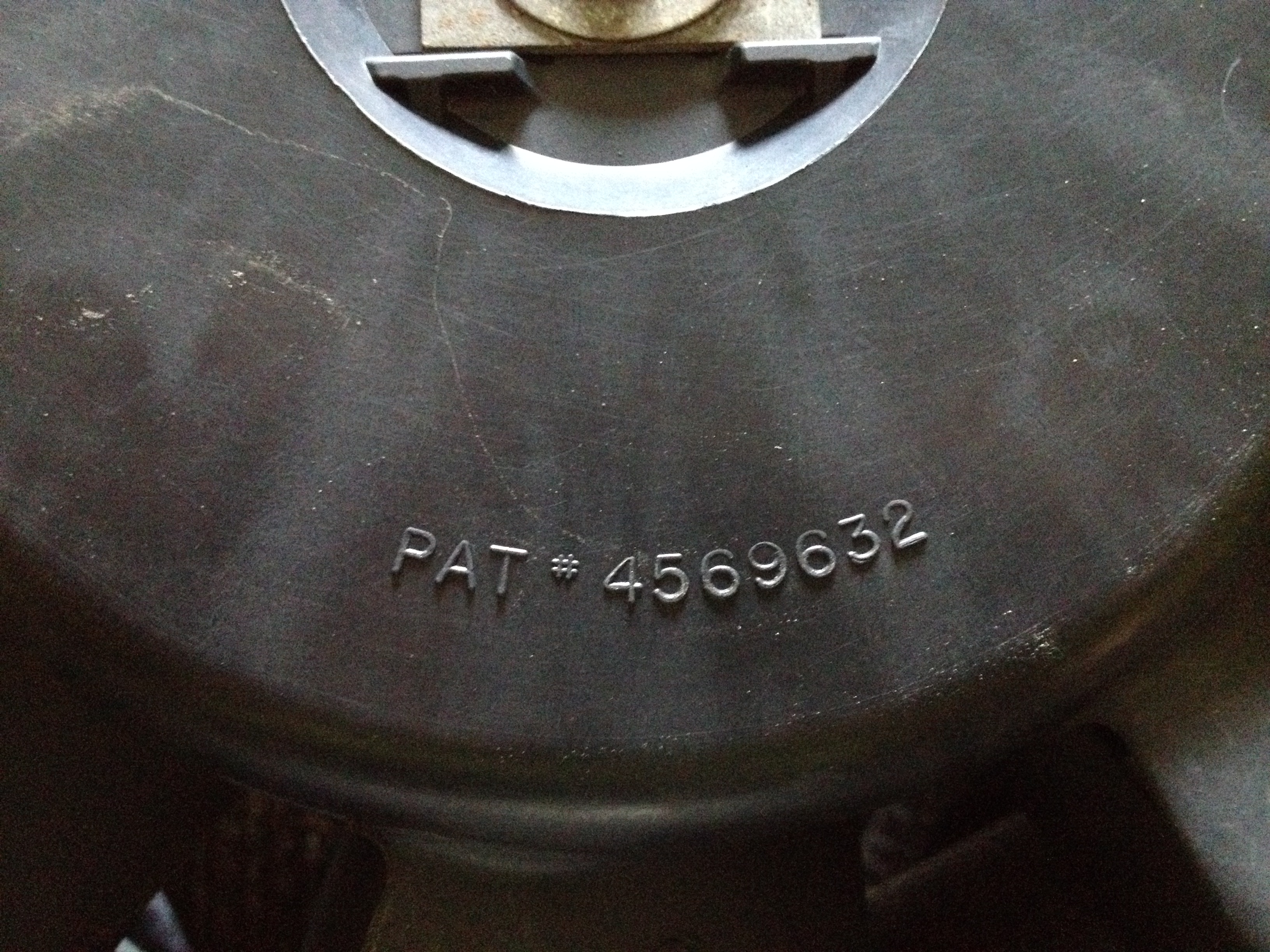

Oddly enough, this fan seems to have an inline circuit breaker. One breaker rated for 20 amps and the other rated for 40. Extra protection, which is nice. There's also three wires. I'd estimate these to be 10-12 awg. They're certainly thick!

Black is ground for both speeds. Brown with orange stripe is low mode and the blue wire is the high side. Thankfully my junkyard allows you to bring batteries inside. Hooked it up and DANG this thing moves some air! I'm tempted to get another fan and make my own standing fan for the garage or something.
So far I'm starting to think that maybe I should have gone with the dual fan setup that the ~03 Taurus uses. That being said, though, I do wish to retain my 3.0 shroud as it's built specifically for this radiator. The shroud on the efan right now will become something akin to an adapter ring to get this fan into the stock fan shroud. We'll just have to see how that plays out. Just waiting on my fuse box and radiator hose adapter for the sensor to get here.
Oddly enough, this fan seems to have an inline circuit breaker. One breaker rated for 20 amps and the other rated for 40. Extra protection, which is nice. There's also three wires. I'd estimate these to be 10-12 awg. They're certainly thick!
Black is ground for both speeds. Brown with orange stripe is low mode and the blue wire is the high side. Thankfully my junkyard allows you to bring batteries inside. Hooked it up and DANG this thing moves some air! I'm tempted to get another fan and make my own standing fan for the garage or something.
So far I'm starting to think that maybe I should have gone with the dual fan setup that the ~03 Taurus uses. That being said, though, I do wish to retain my 3.0 shroud as it's built specifically for this radiator. The shroud on the efan right now will become something akin to an adapter ring to get this fan into the stock fan shroud. We'll just have to see how that plays out. Just waiting on my fuse box and radiator hose adapter for the sensor to get here.


