LED DOOR LOCK INDICATORS! (all models)
#1
 01-16-2010


LED DOOR LOCK INDICATORS! (all models)
this is the thread i am going to be using for the install on my LED door lock indicators, that everyone thought couldn't be done on the new rangers (or old rangers for that matter) this is a basic lever rope and pulley system essentially...
the ups:
can be used on any vehicle with automatic locks,
cheap, parts are worth approx $5 per door
looks awesome
the downs:
fairly labour intensive
does not blink, just a solid light, however read below for a fix to make it blink
that's really it as far as i can see...
the parts required:
2X multi colour LED's (NOT bi-polar) these have to be LED's that have 3+ leads coming out of them, does not matter if it is a common cathode or common annode. make sure you get resisters with them, so they don't burn out...
2X micro lever switches
2X t-1 3/4 holders
wire
heat shrink tubing
disconnect F (female tab connectors)
the tools:
soldering iron,
solder,
lighter,
knife/wirecutters/wirestrippers
the pics and instructions:
ok, i started with the LED's and resisters seen here

i then soldered the resister to the common lead on my LED, which in my case is the Annode, [most others should be cathode (K) ] my annodes are what is going to determine the colour, but i am getting ahead of myself...
next i needed to wire them up, i used a piece of cat 5e cable, which is meant for data, not power, however, LED's use minimal power, so the individual pieces of wire IN the cat 5e is perfect for me... i separated the wire (took a long time) and soldered the wire to each of the cathodes of the LED, and to the resister on the anode:

next is a simple process, i covered EVERYTHING in heat shrink tubing, even the resister, this will make sure nothing grounds out and shorts, or turns the light on the wrong colour or anyother problem that could arise...

after that, i put the t 1-3/4 holder on, just for fun...

without the wires:

next is the switch:

seen here with one of the connectors we will be using:
next, i just crimped the connectors onto the wires(stripping first), all 3 of the anodes, here i have the wire for the red part of the LED connected to the NC portion of the switch, which means the lone pin on the side of the switch is common with red, when the switch is in it's natural position, and i have the blue anode connected to the NO pin, which means it is an open circuit in it's natural position, and closed, when the switch is activated, where as the other is opened when the switch is activated.
thus, giving this result, switch in natural position:

switch activated:
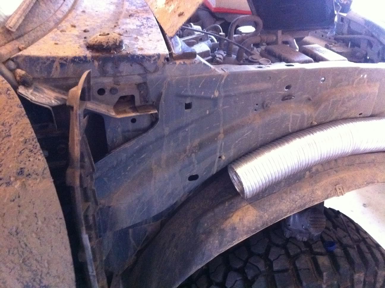
that is it for the build of the LED indicator mod, i can't do the installation right now, as my truck is getting a nose job... but will update this thread as soon as it is back...
it's not hard to do, but the switch replaces the lever used to push the pin up on the door... i had a 12v 1/2 aa sized battery kicking around from some electropods i put on my bike... which is how i tested it...
FLASHING DOOR LIGHTS:
there is a simple way to do this, make up a relay, or find one, that works like a signal flasher (but way smaller) and put it on either the positive wire or the ground wire (which on mine comes off of the switch) hook that relay up, in line, and it will blink constantly, you will probably need one for each door, for now, this is how i am going to leave it, until i source some cheap small flashers, if you are to use 2 flashers, your lights will not flash in sync, if you wanted them to flash together, you will have to run a wire from each door to a central location, put the 2 together onto one lead on the flasher relay, and the other lead of the relay to a positive source... the leads coming off of the circuit, described above, should be coming off the cathode (K)
the ups:
can be used on any vehicle with automatic locks,
cheap, parts are worth approx $5 per door
looks awesome
the downs:
fairly labour intensive
does not blink, just a solid light, however read below for a fix to make it blink
that's really it as far as i can see...
the parts required:
2X multi colour LED's (NOT bi-polar) these have to be LED's that have 3+ leads coming out of them, does not matter if it is a common cathode or common annode. make sure you get resisters with them, so they don't burn out...
2X micro lever switches
2X t-1 3/4 holders
wire
heat shrink tubing
disconnect F (female tab connectors)
the tools:
soldering iron,
solder,
lighter,
knife/wirecutters/wirestrippers
the pics and instructions:
ok, i started with the LED's and resisters seen here
i then soldered the resister to the common lead on my LED, which in my case is the Annode, [most others should be cathode (K) ] my annodes are what is going to determine the colour, but i am getting ahead of myself...
next i needed to wire them up, i used a piece of cat 5e cable, which is meant for data, not power, however, LED's use minimal power, so the individual pieces of wire IN the cat 5e is perfect for me... i separated the wire (took a long time) and soldered the wire to each of the cathodes of the LED, and to the resister on the anode:
next is a simple process, i covered EVERYTHING in heat shrink tubing, even the resister, this will make sure nothing grounds out and shorts, or turns the light on the wrong colour or anyother problem that could arise...
after that, i put the t 1-3/4 holder on, just for fun...
without the wires:
next is the switch:
seen here with one of the connectors we will be using:
next, i just crimped the connectors onto the wires(stripping first), all 3 of the anodes, here i have the wire for the red part of the LED connected to the NC portion of the switch, which means the lone pin on the side of the switch is common with red, when the switch is in it's natural position, and i have the blue anode connected to the NO pin, which means it is an open circuit in it's natural position, and closed, when the switch is activated, where as the other is opened when the switch is activated.
thus, giving this result, switch in natural position:
switch activated:
that is it for the build of the LED indicator mod, i can't do the installation right now, as my truck is getting a nose job... but will update this thread as soon as it is back...
it's not hard to do, but the switch replaces the lever used to push the pin up on the door... i had a 12v 1/2 aa sized battery kicking around from some electropods i put on my bike... which is how i tested it...
FLASHING DOOR LIGHTS:
there is a simple way to do this, make up a relay, or find one, that works like a signal flasher (but way smaller) and put it on either the positive wire or the ground wire (which on mine comes off of the switch) hook that relay up, in line, and it will blink constantly, you will probably need one for each door, for now, this is how i am going to leave it, until i source some cheap small flashers, if you are to use 2 flashers, your lights will not flash in sync, if you wanted them to flash together, you will have to run a wire from each door to a central location, put the 2 together onto one lead on the flasher relay, and the other lead of the relay to a positive source... the leads coming off of the circuit, described above, should be coming off the cathode (K)
Last edited by --weezl--; 01-21-2010 at 01:12 PM.
#2
01-17-2010
Join Date: Aug 2006
Location: btwn the Buff and the Roc
Posts: 1,302
Likes: 0
Received 0 Likes
on
0 Posts
#4
01-18-2010
Join Date: Aug 2006
Location: btwn the Buff and the Roc
Posts: 1,302
Likes: 0
Received 0 Likes
on
0 Posts
anyways looks good.
#8
02-17-2010
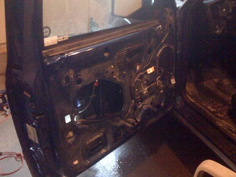
i have now completed what was once thought impossible! :D i have only done one door so far, it took about 4 hours, but that is counting a sandwich break, a lot of time spent swearing and wanting to beat something with a hammer, and thinking, and a trip to home depot for supplies... started by taking off the door pannel, starting with the handle/control area

then take the rest of the door off, there are 2 screws to get to the above step, and 2 additional screws to get to the below step, make sure you are removing the wires from the switched, they are a pain, but how to do it is pretty straight forward when you see them...
now you have to remove the old pin (which we are replacing with the LED) this i did by bending, and prying, and unbolting the actual lock from the door, and a bunch more messing with it... it came off eventually... bolt it back up, and run the wires, my system was already all wired together as 1 unit, so i dropped it through the access hole, and i pulled the LED up through the pin hole in the top...
next i wired it to work, i hooked my positive lead up to the power mirror wire, which was brown and... pink?
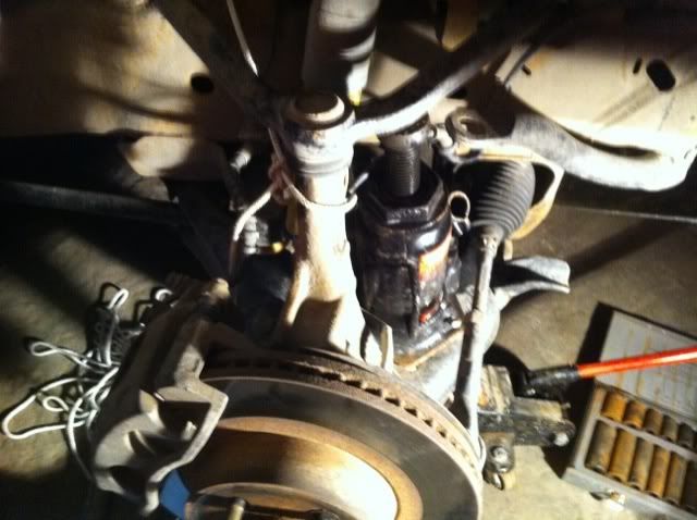

my common lead on my switch was my ground, this was run, using a piece of speaker wire, to a bolt in the door skin (inside) you can see the bolt in one of the pics above.
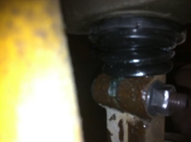
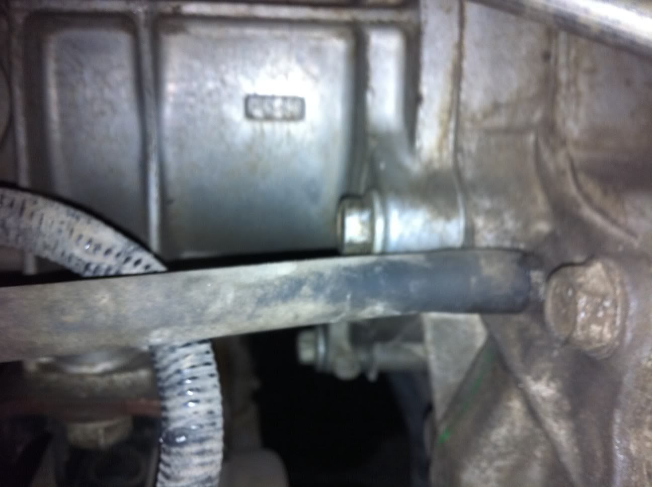
i then glued (yes, glued) the switch into place, i put it just below the lock-catch area, with the lever pointing towards the hinge, a lot of bending on the lever and it looked like this, if you look closely, right below the white gromet looking thing, on the left, there is a silver piece, just below it, vertical, this is the bent lever, and just below that, in the pic, is the switch it's self (you are looking at it from the end)
now that was done, the only thing left to do was put it all back together, and place the light where i want... i used a small dab of krazy glue on the LED to hold it into the bezel, and a small dab of it on the bezel to hold it to the door, it looks like this, i had to disconnect the battery to get this shot (light off)


and i'm done for the night!
then take the rest of the door off, there are 2 screws to get to the above step, and 2 additional screws to get to the below step, make sure you are removing the wires from the switched, they are a pain, but how to do it is pretty straight forward when you see them...
now you have to remove the old pin (which we are replacing with the LED) this i did by bending, and prying, and unbolting the actual lock from the door, and a bunch more messing with it... it came off eventually... bolt it back up, and run the wires, my system was already all wired together as 1 unit, so i dropped it through the access hole, and i pulled the LED up through the pin hole in the top...
next i wired it to work, i hooked my positive lead up to the power mirror wire, which was brown and... pink?
my common lead on my switch was my ground, this was run, using a piece of speaker wire, to a bolt in the door skin (inside) you can see the bolt in one of the pics above.
i then glued (yes, glued) the switch into place, i put it just below the lock-catch area, with the lever pointing towards the hinge, a lot of bending on the lever and it looked like this, if you look closely, right below the white gromet looking thing, on the left, there is a silver piece, just below it, vertical, this is the bent lever, and just below that, in the pic, is the switch it's self (you are looking at it from the end)
now that was done, the only thing left to do was put it all back together, and place the light where i want... i used a small dab of krazy glue on the LED to hold it into the bezel, and a small dab of it on the bezel to hold it to the door, it looks like this, i had to disconnect the battery to get this shot (light off)
and i'm done for the night!
Last edited by --weezl--; 02-17-2010 at 09:52 PM.
#9
02-17-2010
#10
02-17-2010
total cost, less than 10$ including shipping on all parts. assembly of items took about half an hour, and instalation on the first door (which i was guessing the whole way through) was about 3 hours actual work time so you could probably do the entire thing, in 6 hours, start to finish, from parts in boxes from china, japan and tiwan, to being in your truck and looking sweet


#12
02-17-2010
this does not need ANYTHING to make it work, other than electric door locks... if you have electric door locks, you can make this work for you any make, any model, any options
it is a stand-along system which need nothing more than 1 moving part to activate it, and a power source
even if you didn't have a moving part, i could make it work, i was thinking about how to make a "no moving part" door lock and latch system, but i think it would be more work than it's worth...
it is a stand-along system which need nothing more than 1 moving part to activate it, and a power source
even if you didn't have a moving part, i could make it work, i was thinking about how to make a "no moving part" door lock and latch system, but i think it would be more work than it's worth...
#13
02-17-2010
#17
02-17-2010
#18
02-17-2010


#20
02-18-2010
#21
02-18-2010
it's not enough to make them drain the battery, it's only 2 lights, (one each door) the absolute maximum forward current (draw) is 75mA and maximum constant is 30mA so based on the standard car battery being 60Ah which would be the same as 60 000mAh so i it were running flat out, at it's absolute maximum draw, until it ran the battery dead (which wouldn't happen, it would burn the light out, as it's peak draw) it would last, with 2 led's, 400 hours, which is the same as 16 days... at it's maximum constant draw, (30) it would last 1000 hours, which is 41 days, being that it will probably run for real, about 10, it should last 250 days, if i make it blink, it will make it last exponentially longer, not taking into consideration the power it takes to power the flashing unit...
that being said, the receiver unit for your keyless entry would probably draw a considerable amount more...
yes they are, they aren't bad, no worse than a headunit, the LED's project the light out the top, so most of it goes and hits the top of the door frame, i was worried about it at first, but driving to work thismorning, it was just fine, didn't even notice it was there...
#23
02-21-2010
not a dumb question at all... yeap it sure does... i was using my key in the door to test during the install, because the electronic switch on the inside was sitting on the other side of my garage, if you wanted to disconect the key, you could do that too... it's a little more secure...
#24
02-24-2010
Join Date: Jun 2009
Location: Houston, TX
Posts: 136
Likes: 0
Received 0 Likes
on
0 Posts
#25
02-25-2010
not the way it is wired, but if you really wanted to, you could pull the positive from each side back to under the dash, wire them together and onto a switch, then have the other side of the switch connected to positive (i would recommend putting a fuse in place also, if you were to do this)


