


no spark or fuel pressure


Thread Starter
|
Member

Joined: Jun 2010
Posts: 17
Likes: 0
From: kelowna, bc
no spark or fuel pressure
Hey, hoping someone can help me out. i have a 92 ranger XLT 4x4 (had a 4.0L v6 auto) and i've put a '90 302 v8/'75 c4 tranny in her. i've bought off ebay an 89 A9P mustang puter and a wiring harness from a 91 stang. will these work with each other or were there wiring changes from 89 - 91? i've looked but can't find a definite answer anywhere. in the mean time i've gone ahead and bought a harwood manual for my year of ranger and spliced the 91 stang harness into my truck as per the manual (i've left all the ranger wiring in place but taken out the puter). when i turn the key i can crank her over but not getting fuel pressure or spark. i've replaced the relays for the fuel pump and the EEC relay. also everything worked on my truck before i started the swap. i get a check engine light on the dash when i have the key on engine off and it disappears when i unplug the 89 stang puter. i've also tried to jump the plugs for the diag. code plug to get the CEL to blink any codes at me (as per a guide i found on the net) but it wont blink at all, just stays solid. i'm thinking my next step (given that my 89 puter will work with a 91 harness) is to pull out the multimeter and start diagnosing that way. i've double checked pretty much all the plugs and grounds and everything looks good. any suggestions would be much appreciated. thx guys.

The 89 PCM will work with the 91 wiring harness. I have a feeling your troubles are in how the wiring was done. What exactly did you do to the 91 engine harness in order to adapt it to your truck? Did you remove the 4.0 engine harness? The 91 wiring harness is independent of the chassis harness, when I wired mine it primarily needed an ignition hot signal to activate the EEC relay, as well as being grounded. I would start by looking over that harness, especially the transmission wiring. If the trans harness is not hooked up or jumpered properly it will stop the rest of the system, like a clutch switch, or neutral safety switch on an AOD which the 91 would have come with. The A9P computer is an automatic transmission, that might not be working properly if it is not recieving any trans signals.
Thread Starter
|
Member
Joined: Jun 2010
Posts: 17
Likes: 0
From: kelowna, bc
i left all the 4.0 harnesses in except for the engine harness(with the injector plugs, etc) and laid the 5.0L harness in right beside the old harness around the engine compartment. i followed the harwood performance manual on what wires to splice into the C105F plug. at first it wouldn't even crank but then i found the neutral/safety wires on the 4.0 harness and wired them together which allowed the start to work using the ignition. i've thought about the neutral/safety wires on the 5.0L harness but haven't found exactly which ones yet. also i have a 1975 c4 transmission in there so there's no wires coming off that to plug into the 5.0L harness. on a side note i havne't plugged any o2 sensors in yet either so not sure if that is contributing to the problem. figured i would just get some error codes at least.
I'm having a hard time following how you have wired it so far. If you removed the 4.0 engine harness, how did you jump the neutral safety switch? If you haven't properly setup the neutral safety switch on the 5.0 harness its not going to allow the PCM to start, which would cause no fuel or spark. The C4 won't have anything that will electrically connect to the 5.0 harness, but the trans harness that would connect to an AOD needs to be setup properly. The 02 sensors will not stop it from starting.
Thread Starter
|
Member
Joined: Jun 2010
Posts: 17
Likes: 0
From: kelowna, bc
the only 4.0L harness i've removed was the one with the injector plugs, thermostat pressure sender, oil pressure sender, etc. as for the neutral safety switch on the 5.0L harness it looks to me that the white/pink wire and black/white wire are the ones i need to look at but not sure. also how would i setup the trans harness that would connect to an AOD?
I don't have the schematics with me right now to verify the coloring, but the way you would setup the AOD trans harness is basicaly the same as jumpering the safety switch. Its just closing a circuit the AOD normal would when in Park or Neutral so that the PCM sees that it is okay to start. I suggest searching around for some better schematics, I know I have one at home that made my lift alot easier when I wired mine, they are worth their weight in gold.
EDIT: Here is the schematic I had alot of luck with.

EDIT: Here is the schematic I had alot of luck with.

Member
Joined: Oct 2006
Posts: 224
Likes: 0
From: Opa Locka, Fl
I had a similar problem when I first wired the truck, I wasn't getting spark. Thanks to another forum I found out that I didn't have grounded the pcm. Check all your grounds, that solves most of the issues.
Good luck
Good luck
Thread Starter
|
Member
Joined: Jun 2010
Posts: 17
Likes: 0
From: kelowna, bc
Thx for the schematic but the wire colors on my distributor are the same as on this diagram:
http://www.veryuseful.com/mustang/te...ng_Diagram.gif
also, i've checked all my grounds and everything is good from what i can see. i will be checking the park/neutral wires (gray/red and light blue/yellow -> bottom right of the diagram i referenced above). when i was following the harwood manual for wiring it mentioned a 3 wire splice of connecting the R/LB wire from the 5.0L to Pink in C105F and Pink in C116M. i couldn't find where C116M was as it wasn't referenced in the manual anywhere so i just connected the R/LB wire to Pink in C105F. is the 2nd Pink in C116M the Pink in the distributor TFI plug?
http://www.veryuseful.com/mustang/te...ng_Diagram.gif
also, i've checked all my grounds and everything is good from what i can see. i will be checking the park/neutral wires (gray/red and light blue/yellow -> bottom right of the diagram i referenced above). when i was following the harwood manual for wiring it mentioned a 3 wire splice of connecting the R/LB wire from the 5.0L to Pink in C105F and Pink in C116M. i couldn't find where C116M was as it wasn't referenced in the manual anywhere so i just connected the R/LB wire to Pink in C105F. is the 2nd Pink in C116M the Pink in the distributor TFI plug?
Last edited by tripp; Jun 23, 2010 at 12:23 PM.

Member
Joined: Oct 2006
Posts: 224
Likes: 0
From: Opa Locka, Fl
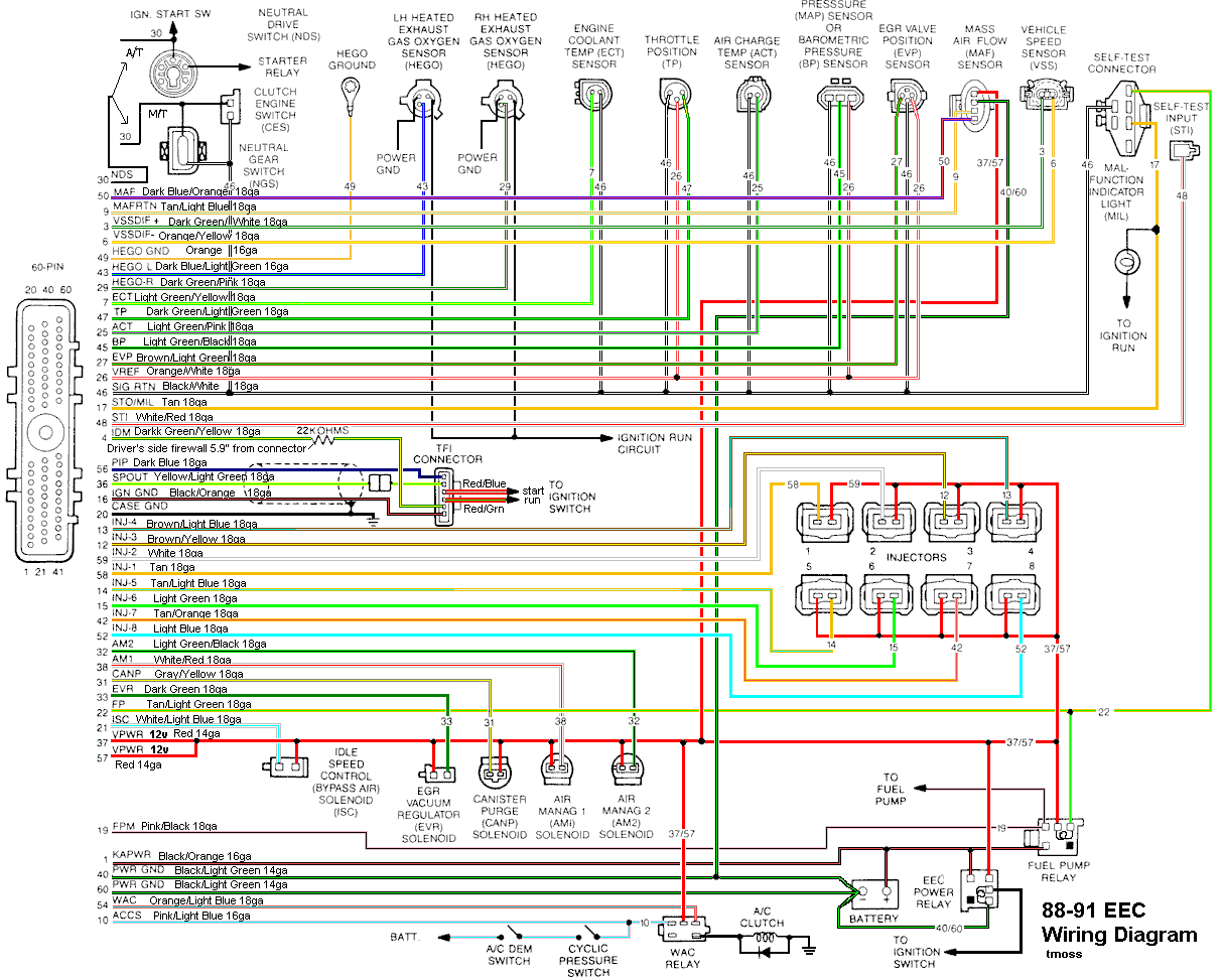
Again check your main grounds. Get a multimeter and measure the continuity of pins 16, 20, 40 and 60 on the pcm connector to the chassis or the body. If you get ground on all of those then check for power, turn ignition on and check pins 37, 50, 1, 19. Also on the distributor connector check both RED/BLUE and RED/GRN wires for power. Just in case, do it without the pcm connected!!
Also this is a plus. When you get everything running, remember to ground the motor and the body to the chassis if you haven't done it.
Good luck!!
Thread Starter
|
Member
Joined: Jun 2010
Posts: 17
Likes: 0
From: kelowna, bc
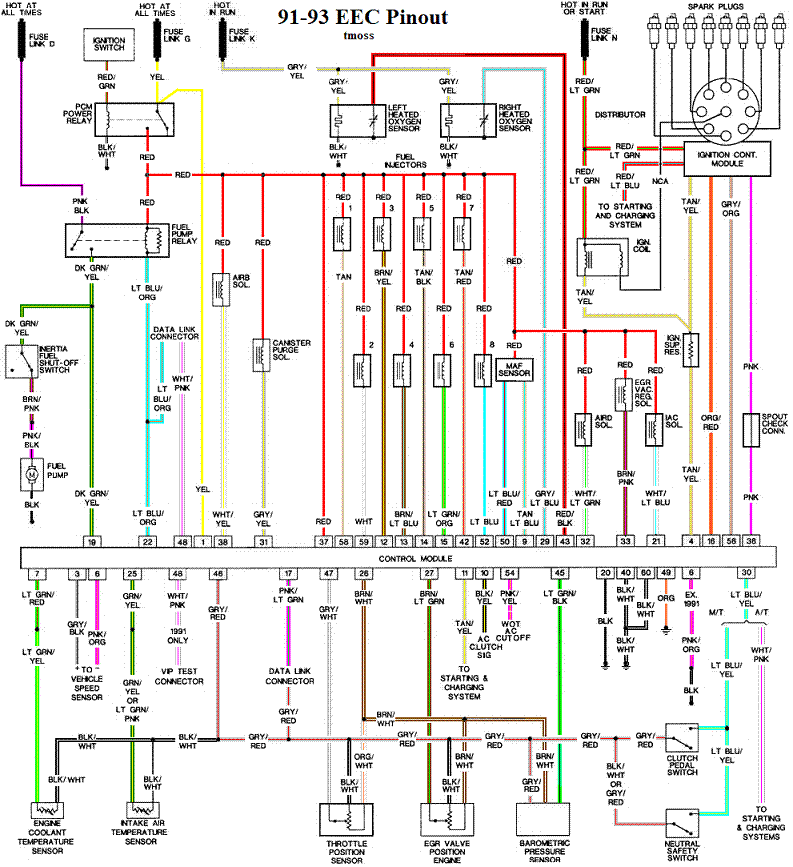
well i've gone through the pins you suggested and all the grounds had continuity. as for power the yellow wire, pin 1, i found out wasn't hot all the time as well as one of the wires coming off the fuel relay wasn't wired hot at all times either. so i fixed that up and now i have fuel pressure. but still no spark. i checked the ignition module and the red/green has 12v and the tan/yellow wire has almost 5v. is the tan/yellow supposed to have 5v? also i have a 75 c4 transmission and no neutral safety switch so i was thinking that may have something to do with it but not sure what wires to wire together.
so to recap:
- all my grounds you suggested have continuity
- all my pwr wires you suggested have pwr(now that i fixed it)
- i have fuel pressure now but no spark still
- the red/blue and red/green have pwr at the distributor
-the red/green has power at the ignition coil
-the tan/yellow has 5v at the ignition coil (not sure if it should have 5v)
-the neutral/safety switch wires blue/yellow(pin30) and gray/red i think should be wired together...but not sure.
Thread Starter
|
Member
Joined: Jun 2010
Posts: 17
Likes: 0
From: kelowna, bc
ok i'm stumped guys. as mentioned above i've checked the continuity of pins 16, 20, 40 and 60 and they're good. I've checked pins 37, 50, 1, 19 and there was an issue with pin 1 not having 12v so i fixed that and now its good and i have fuel pressure. I"ve checked both RED/BLUE and RED/GRN wires for power and they do (Red/blue constant 12v, Red/LG is 12V when key ON/engine OFF).
so now i have fuel pressure but no spark still. i've gone thru this worksheet:
http://www.therangerstation.com/tech..._worksheet.jpg
and everything is as it should be voltage, continuity, and resistance wise. but i'm still not getting a spark. i have a spark tester in between the ignition module and the center post of the distributor to see if i'm getting a spark and i'm not. i've also replaced the ignition module.
i'm getting 12v on both the + and - sides of the ignition module and when i crank it over they both drop down to 8-9v (as the worksheet says) and fluctuate around there.
any help would be appreciated as i'm super stumped.
so now i have fuel pressure but no spark still. i've gone thru this worksheet:
http://www.therangerstation.com/tech..._worksheet.jpg
and everything is as it should be voltage, continuity, and resistance wise. but i'm still not getting a spark. i have a spark tester in between the ignition module and the center post of the distributor to see if i'm getting a spark and i'm not. i've also replaced the ignition module.
i'm getting 12v on both the + and - sides of the ignition module and when i crank it over they both drop down to 8-9v (as the worksheet says) and fluctuate around there.
any help would be appreciated as i'm super stumped.
Member
Joined: Oct 2006
Posts: 224
Likes: 0
From: Opa Locka, Fl
Check if you are getting voltage to the coil. Also this on is kinda hard to test but it happened to me. Sometimes the truck started without no problems but then sometimes it crank but the were no spark, the stator inside the distributor sometimes it goes bad (opens) if you have a spare distributor try it if not you might hav to go get one on discount auto parts.
Good luck!!!!!!
Good luck!!!!!!
Thread Starter
|
Member
Joined: Jun 2010
Posts: 17
Likes: 0
From: kelowna, bc
yup i'm getting 12v on both + and - of the ignition coil. when i put inthe test light the - side drops down the 8-9v when cranking and the test light pulses. it does the same thing on the + side which i can't find anywhere whether thats good or bad.
Member
Joined: Oct 2006
Posts: 224
Likes: 0
From: Opa Locka, Fl
When i get home i'll test the coil wires in my truck while I crank it. I don't know if you are suppost to have 12v on both wires though BUT either way it sounds that you have a a stator or maybe the coil is bad. Can you swap the coil atleast?
Good luck
Good luck
Thread Starter
|
Member
Joined: Jun 2010
Posts: 17
Likes: 0
From: kelowna, bc
i've already swapped out the coil and same thing. from what i've read the positive side should be a constant 12v and the neg side is 12v and should "pulse" the test light when cranking. but ya if you could check yours that would be awesome man. thx.
Member
Joined: Oct 2006
Posts: 224
Likes: 0
From: Opa Locka, Fl
Im sorry bro, I work at nightshifts so i haven't got the time to check the coil wires but I did check the distributor wires and i got the same thing as you, so I believe that your wiring on the distributor is good. BTW I bought my msd pro bullet distributor brand spanking new and the stator inside was bad, so don't think because you have a new product is not defective. I had to call msd itself and they told me to change the stator which I did and I've never had a problem after that but is definitely a pain in the a$$.
I'll check the voltage later today and i'll let you know if is the same as yours.
I'll check the voltage later today and i'll let you know if is the same as yours.


