What wire do I tap into?
#1
 09-04-2009


Join Date: Jun 2009
Location: Beaumont, CA
Posts: 632
Likes: 0
Received 0 Likes
on
0 Posts
What wire do I tap into?
I want to have my A/C power an efan relay, what wire do I tap into on my 05 3.0? I know I have to wire in a diode, but does the silver band go towards the relay or clutch? I think it goes towards relay, but not sure. 
Relay -----|<---- A/C clutch.................right?
Relay -----|<---- A/C clutch.................right?
#2
09-05-2009

Join Date: May 2009
Location: Kansas City, MO
Posts: 380
Likes: 0
Received 0 Likes
on
0 Posts
#3
09-05-2009

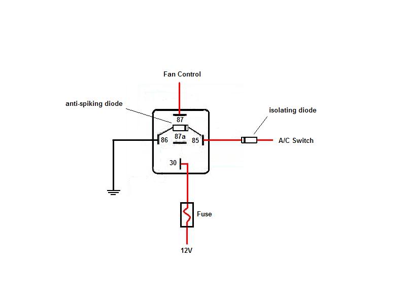
I don�t have an 05 schematic but, if the AC control switch works similar to an 01 (sends power signal to PCM) you could tap it to send a positive signal to the relay coil. However, you�d need to install an anti-spiking diode between relay terminals 85 and 86 and an isolating diode inline between the switch tap and the relay as shown in pic 1.
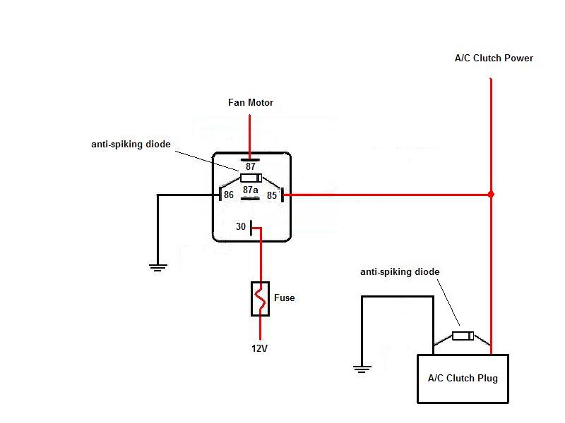
You can also tap the A/C Clutch power feed to control the relay. However, if the clutch does not have a built in anti-spiking diode I�d strongly recommend installing one at the plug as shown in pc 2.
Make sure the relay and fuse are rated to handle the current the fan will draw plus 10%.
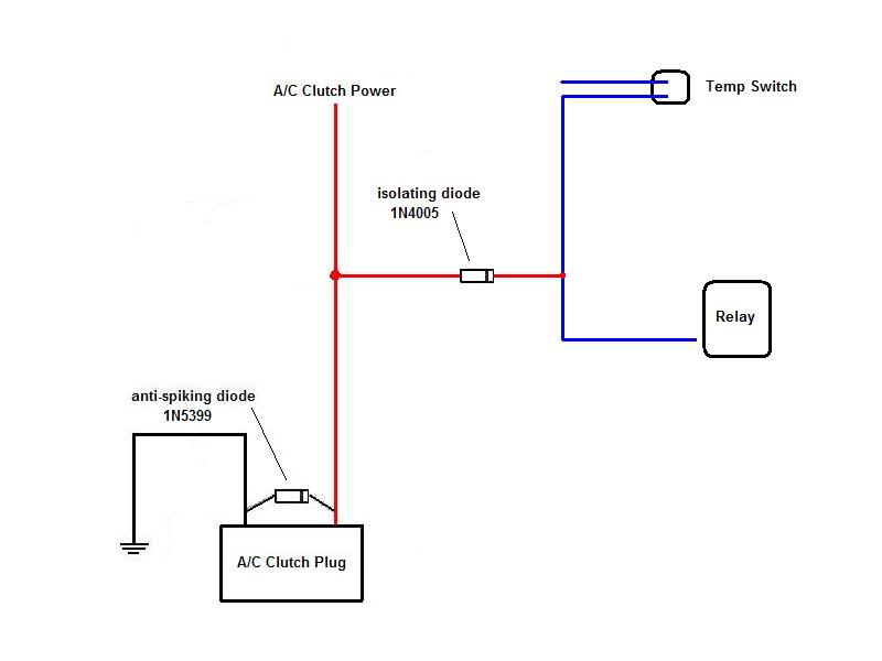
Recommend using 1N4005 diodes for relay and 1N5399 at A/C clutch plug. You can pick them up from Radio Shack.
You can also tap the A/C Clutch power feed to control the relay. However, if the clutch does not have a built in anti-spiking diode I�d strongly recommend installing one at the plug as shown in pc 2.
Make sure the relay and fuse are rated to handle the current the fan will draw plus 10%.
Recommend using 1N4005 diodes for relay and 1N5399 at A/C clutch plug. You can pick them up from Radio Shack.
#4
09-07-2009
Join Date: Jun 2009
Location: Beaumont, CA
Posts: 632
Likes: 0
Received 0 Likes
on
0 Posts
I don�t have an 05 schematic but, if the AC control switch works similar to an 01 (sends power signal to PCM) you could tap it to send a positive signal to the relay coil. However, you�d need to install an anti-spiking diode between relay terminals 85 and 86 and an isolating diode inline between the switch tap and the relay as shown in pic 1.
[IMG]http://i224.photobucket.com/albums/dd303/revinsd/FanRelay.jpg[IMG]
You can also tap the A/C Clutch power feed to control the relay. However, if the clutch does not have a built in anti-spiking diode I�d strongly recommend installing one at the plug as shown in pc 2.
[IMG]http://i224.photobucket.com/albums/dd303/revinsd/FanRelay2.jpg[IMG]
Make sure the relay and fuse are rated to handle the current the fan will draw plus 10%.
Recommend using 1N4005 diodes for relay and 1N5399 at A/C clutch plug. You can pick them up from Radio Shack.
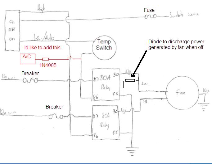
Ive also got a "free spinning diode" going from the LO power wire off the fan to a ground, is that what you mean by anti-spiking diode? I'll draw up my schematic so you know how Im running my fans.
#5
09-07-2009
Join Date: Jun 2009
Location: Beaumont, CA
Posts: 632
Likes: 0
Received 0 Likes
on
0 Posts
#6
09-07-2009
#7
09-07-2009
Join Date: Jun 2009
Location: Beaumont, CA
Posts: 632
Likes: 0
Received 0 Likes
on
0 Posts
#8
09-08-2009
Join Date: Jun 2009
Location: Beaumont, CA
Posts: 632
Likes: 0
Received 0 Likes
on
0 Posts

#9
09-08-2009
Join Date: May 2009
Location: Kansas City, MO
Posts: 380
Likes: 0
Received 0 Likes
on
0 Posts

#10
09-08-2009
Join Date: Jun 2009
Location: Beaumont, CA
Posts: 632
Likes: 0
Received 0 Likes
on
0 Posts
Looks like a good setup, I just wanted to have my relays independent of each other. That way, if say the LO relay fails, I can still power up the HI side. I didnt draw them there, but I have LEDs hooked up to the wires powering up the fan, just to make sure I know when the fan is getting power. Thanks for sharing though, maybe now you can use the diodes Im using/will use.
#11
09-08-2009
Join Date: May 2009
Location: Kansas City, MO
Posts: 380
Likes: 0
Received 0 Likes
on
0 Posts
#12
09-08-2009
Join Date: Jun 2009
Location: Beaumont, CA
Posts: 632
Likes: 0
Received 0 Likes
on
0 Posts
Im using a 210 on - 200 off temp switch from indexsensors.com. I think you edited your post before I got here, but the switch will power the relay once it reaches 210 and will cut power once it goes back down to 200.
I dont know why the truck would be on if Im not inside, but my toggle switch is always on the LO/AUTO position where the fan will come on at that time. Ive been in 105F heat, idling and A/C on full blast and the fan was able to cool it down to 200, no problem. Ive yet to use HI
 If Im driving and notice temps are not coming down, I can flip it to HI, control the temp and then switch back to auto.
#13
09-08-2009
The 1N5407 should work other than its physical size is a little large. Yes you want to install it between the GY/WH and BK wire (band towards the GY/WH) just above the plug and insulate it as needed (recommend soldering). If your cluster has a high temp idiot light you could tie into its circuit using a transistor to trip the high speed relay just in case.
#14
09-08-2009
Join Date: Jun 2009
Location: Beaumont, CA
Posts: 632
Likes: 0
Received 0 Likes
on
0 Posts
The 1N5407 should work other than its physical size is a little large. Yes you want to install it between the GY/WH and BK wire (band towards the GY/WH) just above the plug and insulate it as needed (recommend soldering). If your cluster has a high temp idiot light you could tie into its circuit using a transistor to trip the high speed relay just in case.
#15
09-08-2009
Join Date: May 2009
Location: Kansas City, MO
Posts: 380
Likes: 0
Received 0 Likes
on
0 Posts
#16
09-08-2009
Join Date: Jun 2009
Location: Beaumont, CA
Posts: 632
Likes: 0
Received 0 Likes
on
0 Posts
#18
09-08-2009
Join Date: Jun 2009
Location: Beaumont, CA
Posts: 632
Likes: 0
Received 0 Likes
on
0 Posts
yup, thats why I dont have them wired that way. I think that both leads from the fan are powered once on HI though. The reason I say this is because when I wired up my LEDs, I did the LO one first and the light comes on on LO & HI. IDK if powering both leads would kill the motor faster or not, but thats what Ive noticed.
#19
09-08-2009
Join Date: Jun 2009
Location: Beaumont, CA
Posts: 632
Likes: 0
Received 0 Likes
on
0 Posts
#20
09-08-2009
Join Date: Jun 2009
Location: Beaumont, CA
Posts: 632
Likes: 0
Received 0 Likes
on
0 Posts
Just realized that the company I used for my sensor also makes dual setting temp switches http://www.indexsensors.com/pdfs/el_temp_cp.pdf

Thread
Thread Starter
Forum
Replies
Last Post
tractorman
General Technical & Electrical
11
07-15-2010 07:56 AM
WowMike2001
General Technical & Electrical
13
08-16-2009 07:41 AM


