
Dpst relay?

Joined: Sep 2009
Posts: 3,139
Likes: 1
From: Calgary AB, Canada
Dpst relay?
I need help finding an item, I need a relay that will work as a double pole single throw switch, so essentially it allows voltage through one lead, let's call this lead A, but when voltage is applied to the signal wire, lead A loses voltage, and applies voltage to lead B, alternately, I could wire it so that the relay just cuts power from lead a, when the signal wire is activated...
Anyone know what this would be called? Or how to find it on eBay?
Anyone know what this would be called? Or how to find it on eBay?

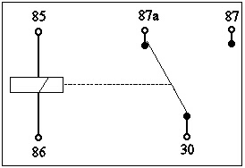
Use a standard 5-pin Bosch-type "automotive" relay, available at any parts store.
Pins 86 and 85 are positive and negative for the relay coil.
30 has continuity to 87a when voltage is not applied across 86 to 85
30 has continuity to 87 when voltage is applied across 86 to 85
Pins 86 and 85 are positive and negative for the relay coil.
30 has continuity to 87a when voltage is not applied across 86 to 85
30 has continuity to 87 when voltage is applied across 86 to 85
Joined: Sep 2009
Posts: 3,139
Likes: 1
From: Calgary AB, Canada
EXACTLY what i was looking for! i had this idea that would work, and it was using a relay identical, except without 87, i'll post it later, when i get all these parts together and make up what i'm doing...
so essentially, 85 is ground, 86 is signal, when 86 gets power, 87 gets power, right? (as long as 30 is constant) so you if 87a were not used, this relay, could be removed, and the input to 86 could just be jumped to 87? i think i am making it more complicated than i need to...
the pinouts, (30, 85, 86, 87a, 87) are all the same across brands right? if i were to say, find a tridon 5 pin, with pins 30, 85, 86, 87a and 87 it would be a direct replacement?
i found one on ebay, with these spesifications...
Rating: 12V DC
Type: SPDT: Single Pole Double Throw
Coil Resistance: 90 Ohms
Coil Inductance 0.8H
Dielectric Strength: 500V RMS
Electrical Life: Quality tested to 100,000 cycles at 40A, 10 Million operations
Temperature Range -40�C ~ 125�C
Inital Operating Data 7 milliseconds
now, 12v, i need, so that's good, type, not so sure, but i'm pretty sure this is right, right? coil resistance, the lower this is, the less it will drain my battery, right? it's going to be hooked to constant power on pin 30, and is only powering 1 led, so minimal power consumption and handling is required, coil inductance, resista,cem dielectric strength, and life aren't going to make much of a difference to me, i don't think... neither will the operating time (7ms) even 1 second would be fine... tempature range, i need to be -40 to where ever... it get's damn cold here... this relay is a little heavy duty for me, isn't it?
Last edited by --weezl--; Dec 26, 2009 at 11:11 PM.
Joined: Sep 2009
Posts: 3,139
Likes: 1
From: Calgary AB, Canada
**** it, i'm just going to post this, and if people figure it out, it's fine... here is the schematic i have drawn up, sorry it's so dark... anyways, please take a look at it before reading below the picture, as it is what the circuit SHOULD do, i want you to see what you think it will do, before you see my adaptation of it... the box in the middle, is the relay that is posted above...
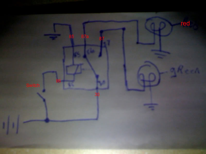
what it should do, is give power to to the red light normally, but when the switch is closed, (turned on) it will give power to the green light... anyone have any thoughts?
what it should do, is give power to to the red light normally, but when the switch is closed, (turned on) it will give power to the green light... anyone have any thoughts?
Member

Joined: Oct 2009
Posts: 274
Likes: 0
From: Fernridge, BC
Those relays are about $5 at CT, or pretty much any other automotive store. Pretty common, most are rated for 30 amps.
I think I see what you're getting at here, I'm not 100% without building a quick circuit myself and trying it out, but you should be right. Worst case you might have to reverse 87 and 87a or something like that. LR
I think I see what you're getting at here, I'm not 100% without building a quick circuit myself and trying it out, but you should be right. Worst case you might have to reverse 87 and 87a or something like that. LR
Joined: Sep 2009
Posts: 3,139
Likes: 1
From: Calgary AB, Canada
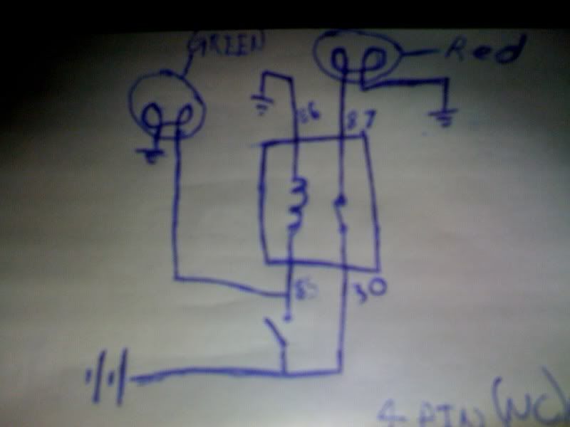
ya, i can deal with that issue... i just didn't want to put all the effort into getting the stuff, and having an epic fail... i also drew up another one here... using a 4 pin NC relay, which should do the exact same thing...


First picture:
Switch closed = green on
Switch open = red on
Second picture will do the same IF the relay used is NC as you said. FWIW, all of the 4-pin Bosch-style automotive relays that I've seen with the 85, 86, 87 and 30 pins are NO between 30 and 87. You could do the same thing with a 5-pin Bosch-style relay by substituting 87A for 87 in the drawing because 30 to 87A is NC.
Joined: Sep 2009
Posts: 3,139
Likes: 1
From: Calgary AB, Canada
i'm going to see if i can find a couple 5 pin micro relay, in which case the pin outs will be different, 85=1, 86=2, 30=3, 87a=4. 87=5. and see how small of amperage i can get, just to keep it from draining the battery, as this really doesn't need a relay, all it needs is a spdt switch, but the switch i am using, is very spesific...
Joined: Sep 2009
Posts: 3,139
Likes: 1
From: Calgary AB, Canada
so turns out, the switch i am using, is an NC/NO switch, so it will do the work of the relay... so delete the relay all together...
different question, still wiring though, i bought 10 of these switches off ebay, except 12v...
LED PUSH BUTTON BRASS DPDT ON/OFF/ON SWITCH 24V,R22ZE on eBay.ca (item 120509305175 end time 29-Dec-09 04:21:32 EST)
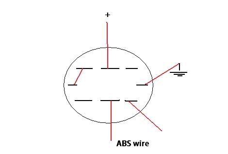
now my question is, how should they be wired, i want the LED to be ON when the item being controlled is OFF, here is what i think it should be... as there is 8 pins, i figure 3 for each pole, and 2 for the LED...
i'm using it for my abs disconnect, to turn my abs off... the black lines are the pins, the red lines are wires... and of course there are lables as to where they go... i do not have a wiring diagram for the switch right now, but assume there will be one that comes with the switch...
different question, still wiring though, i bought 10 of these switches off ebay, except 12v...
LED PUSH BUTTON BRASS DPDT ON/OFF/ON SWITCH 24V,R22ZE on eBay.ca (item 120509305175 end time 29-Dec-09 04:21:32 EST)
now my question is, how should they be wired, i want the LED to be ON when the item being controlled is OFF, here is what i think it should be... as there is 8 pins, i figure 3 for each pole, and 2 for the LED...
i'm using it for my abs disconnect, to turn my abs off... the black lines are the pins, the red lines are wires... and of course there are lables as to where they go... i do not have a wiring diagram for the switch right now, but assume there will be one that comes with the switch...

Thread
Thread Starter
Forum
Replies
Last Post
rngprerunner
General Ford Ranger Discussion
19
Nov 10, 2024 03:09 PM
cheese_man
General Technical & Electrical
1
Jul 18, 2014 03:25 AM
mjktg99
General Technical & Electrical
8
Feb 3, 2006 08:31 AM


