


Need help with Wiring... Electrical..

Thread Starter
|
Member

Joined: May 2004
Posts: 4,508
Likes: 1
From: Smackdownville Tx
Need help with Wiring... Electrical..
Im trying to wire up my alarm, and i ran into alittle problem, i need to know which wires to use to make the doors unlock with the keypad, i dont know which wires to use.
If someone could help me out,
Ill explain the color codes, so you can tell me which colors to use. If someone knows.
From the left of the actuators comes pnk/blk , from the right of the actuators comes pnk/org.
the rh door lock switch has the pnk/blk and pnk/org wires going into it. And from the rh switch to the lh switch are pnk/lt grn and pnk/yel ..
Any idea on which color wires to use? The wires from the actul actuators or the wires from the switches.
Any help is greatly appreciated, attached is a diagram to give you an idea quick drawn in multisim.
If someone could help me out,
Ill explain the color codes, so you can tell me which colors to use. If someone knows.
From the left of the actuators comes pnk/blk , from the right of the actuators comes pnk/org.
the rh door lock switch has the pnk/blk and pnk/org wires going into it. And from the rh switch to the lh switch are pnk/lt grn and pnk/yel ..
Any idea on which color wires to use? The wires from the actul actuators or the wires from the switches.
Any help is greatly appreciated, attached is a diagram to give you an idea quick drawn in multisim.
RF Veteran
Joined: Jun 2004
Posts: 10,623
Likes: 6
From: Kennett Square, PA

That diagram isn't right, Leo. I'll look up the wire colors for you vehicle a little later -- but it is for your '87 'Stang, yes?
The way that has been drawn, nothing will ever happen with the actuators -- which should be drawn as motors, or relays, or some kind of load rather than a switch. I'm not familiar with multisim, but if it's an electrical modeler, it won't correctly analyze the circuit with the actuators shown like that.
You can probably find what you need on http://www.the12volt.com -- that's where I find most of this stuff. There are "typical" control schematics over there, as well as wiring charts for many specific vehicles.
The way that has been drawn, nothing will ever happen with the actuators -- which should be drawn as motors, or relays, or some kind of load rather than a switch. I'm not familiar with multisim, but if it's an electrical modeler, it won't correctly analyze the circuit with the actuators shown like that.
You can probably find what you need on http://www.the12volt.com -- that's where I find most of this stuff. There are "typical" control schematics over there, as well as wiring charts for many specific vehicles.
Leo, there are some problems in that diagram. For one thing, it has the hot wired directly to ground. ???
Rangers from the late eighties reverse the polarity between the pink/orange and pink/black to actuate the door locks.
The commands are:
pink/orange positive, pink/black negative to lock.
pink/black positive, pink/orange negative to unlock.
BUT>>> both wires go to ground state when the door switches are at rest. Meaning that you can't just tap into them - the hot would short to ground.
Here's the 89 Ranger diagram. I'm betting that your Mustang is similar.

Rangers from the late eighties reverse the polarity between the pink/orange and pink/black to actuate the door locks.
The commands are:
pink/orange positive, pink/black negative to lock.
pink/black positive, pink/orange negative to unlock.
BUT>>> both wires go to ground state when the door switches are at rest. Meaning that you can't just tap into them - the hot would short to ground.
Here's the 89 Ranger diagram. I'm betting that your Mustang is similar.
Last edited by V8 Level II; Oct 27, 2005 at 06:31 AM.
Yup, it's the same idea as the 89 Ranger/Bronco II diagram I posted. You will need to add a little extra to interface the alarm to the locks.
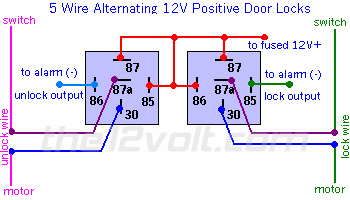
http://www.the12volt.com/doorlocks/page3.asp#5w
I think this will do it. If you only want the unlock function, you only need the relay on the left side. The wire on the far left is the pink/black or the pink/yellow. The "fused +12v" is the black/white.
http://www.the12volt.com/doorlocks/page3.asp#5w
I think this will do it. If you only want the unlock function, you only need the relay on the left side. The wire on the far left is the pink/black or the pink/yellow. The "fused +12v" is the black/white.

Thread Starter
|
Member
Joined: May 2004
Posts: 4,508
Likes: 1
From: Smackdownville Tx
Originally Posted by rwenzing
Yup, it's the same idea as the 89 Ranger/Bronco II diagram I posted. You will need to add a little extra to interface the alarm to the locks.
http://www.the12volt.com/doorlocks/page3.asp#5w
I think this will do it. If you only want the unlock function, you only need the relay on the left side. The wire on the far left is the pink/black or the pink/yellow. The "fused +12v" is the black/white.
http://www.the12volt.com/doorlocks/page3.asp#5w
I think this will do it. If you only want the unlock function, you only need the relay on the left side. The wire on the far left is the pink/black or the pink/yellow. The "fused +12v" is the black/white.
Originally Posted by FoMoCoStang
well, when i said unlock with the keypad, i meant lock as well... Thanks Bob.
I should mention that I was going by the logic in the 89 Ranger diagram to decide which wire is positive for lock and which is positive for unlock. Your Mustang diagram does not indicate which is which. I guess there is a remote chance that the Mustang is the reverse of the Ranger but I doubt it.

Thread
Thread Starter
Forum
Replies
Last Post
winks
General Technical & Electrical
37
Sep 29, 2016 07:24 PM
For Sale: One 2002 Electrical wiring diagram-WA
Sean007
OLD - Interior, Exterior, Electrical, & Misc.
3
Jan 4, 2014 03:09 PM
pacodiablo
General Technical & Electrical
10
Jul 17, 2006 01:08 AM
TippnOver
General Technical & Electrical
12
Nov 10, 2005 01:52 PM


