General Technical & Electrical General technical and electrical discussion for the Ford Ranger that does not fit in any other sub-forum.

Switch wiring help....

Thread Tools
 
Search this Thread
 
  #1  
Old 07-07-2007
lifted97ranger's Avatar
Member
Thread Starter
Join Date: Nov 2005
Location: Charlestown, IN
Posts: 1
Likes: 0
Received 4 Likes on 4 Posts
Switch wiring help....

I need some switch wiring help. I currently have my blue lights, wig-wags, and strobes wired into 1 switch. I want to break that down into a 3 switch setup: 1 Master Switch (which will control blue lights all the time), 1 switch for the wig-wags (wig-wags only on when Master switch and wig-wag switch is on), and 1 for my strobes (same as wig-wag switch).....

Here is the SPST (i can get SPDT, DPST, or DPDT switches if need be) switch i will be using: (the Master switch ONLY will have a blue LED in the switch to show that the lights are on)


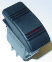
I would prefer to use relays to supply power to the lights.

Here is a diagram that i have drawn up to show the switch locations:
 
  #2  
Old 07-07-2007
doc's Avatar
doc
doc is offline
Member
Join Date: Jun 2004
Location: Media, PA
Posts: 1,406
Likes: 0
Received 0 Likes on 0 Posts
My best guess would be have the master switch be wired to do 2 things: 1:APPLY the 12v power to the relays for the wig wag and strobes (so now they can be activated by their respective switches by applying the power to their trigger) and
2:ACTIVATE the relay for the blues by applying the power to the trigger.
 
  #3  
Old 07-08-2007
heaton84's Avatar
Member
iTrader: (1)
Join Date: May 2006
Location: Portage, IN
Posts: 350
Likes: 0
Received 0 Likes on 0 Posts


Wire up the blue lights normally. Tap the switched hot side of that switch and use it as in input to the other switches, which will then control the other relays. Are you switching on hot or on ground?
 
  #4  
Old 07-08-2007
lifted97ranger's Avatar
Member
Thread Starter
Join Date: Nov 2005
Location: Charlestown, IN
Posts: 1
Likes: 0
Received 4 Likes on 4 Posts
Originally Posted by heaton84


Wire up the blue lights normally. Tap the switched hot side of that switch and use it as in input to the other switches, which will then control the other relays. Are you switching on hot or on ground?
i am switching on the hot side.....
 
  #5  
Old 07-08-2007
Takeda's Avatar
Level I Supporter
Join Date: Aug 2006
Location: Durham, NC
Posts: 3,657
Likes: 0
Received 7 Likes on 3 Posts
Are you controlling relays with these switches, or the lights directly?
 
  #6  
Old 07-08-2007
lifted97ranger's Avatar
Member
Thread Starter
Join Date: Nov 2005
Location: Charlestown, IN
Posts: 1
Likes: 0
Received 4 Likes on 4 Posts
haven't decided if i am going to control them directly or use relays......don't know which would be best (and easiest)......probably will wind up being directly since i have no clue on what spots on a SPST relay are for....
 
  #7  
Old 07-08-2007
Takeda's Avatar
Level I Supporter
Join Date: Aug 2006
Location: Durham, NC
Posts: 3,657
Likes: 0
Received 7 Likes on 3 Posts
If you don't use relays, be careful with the current ratings on the switches. If you want the "blue lights" switch to be able to shut all the lights off, it will be carrying the current for all 3 different sets of lights.
 
  #8  
Old 07-08-2007
lifted97ranger's Avatar
Member
Thread Starter
Join Date: Nov 2005
Location: Charlestown, IN
Posts: 1
Likes: 0
Received 4 Likes on 4 Posts
all the lights currently are ran off a 20A circuit......since all the blue lights are LED's total they draw only 6A....my wig-wags draw 5A and the strobes draw 5A.......the switchs that i am getting are rated at 20A....

how would i wire a relay for the lights? like what pin on the SPST relay would be for what?
 
  #9  
Old 07-08-2007
lowep's Avatar
Member
Join Date: Oct 2006
Location: Gulfport, MS
Posts: 22
Likes: 0
Received 0 Likes on 0 Posts
It's been a few years but I believe this is what it would look like.
 
  #10  
Old 07-08-2007
lifted97ranger's Avatar
Member
Thread Starter
Join Date: Nov 2005
Location: Charlestown, IN
Posts: 1
Likes: 0
Received 4 Likes on 4 Posts
could i use a SPDT relay for the Master switch and use the second 87 pin to send power to the other switches instead of tapping off the wire going to pin 85? wouldn't that be more feasable and safer?
 
  #11  
Old 07-08-2007
Takeda's Avatar
Level I Supporter
Join Date: Aug 2006
Location: Durham, NC
Posts: 3,657
Likes: 0
Received 7 Likes on 3 Posts
Originally Posted by lifted97ranger
could i use a SPDT relay for the Master switch and use the second 87 pin to send power to the other switches instead of tapping off the wire going to pin 85? wouldn't that be more feasable and safer?

Use the first relay, but power the wig-wag, and strobe switches from pin 87 on the relay.
 
  #12  
Old 07-08-2007
lifted97ranger's Avatar
Member
Thread Starter
Join Date: Nov 2005
Location: Charlestown, IN
Posts: 1
Likes: 0
Received 4 Likes on 4 Posts
Originally Posted by Takeda
Use the first relay, but power the wig-wag, and strobe switches from pin 87 on the relay.
correct because a SPDT relay has 2 87 pins......right
 
  #13  
Old 07-08-2007
lowep's Avatar
Member
Join Date: Oct 2006
Location: Gulfport, MS
Posts: 22
Likes: 0
Received 0 Likes on 0 Posts
On a SPDT with no current on the 85 pin, pin 30 and pin 87A from a circuit. When a current is applied to pin 85 pin 30 and pin 87 make a circuit so you couldn't use it that way. As for branching off the main switch to power the other switches there should be such a low draw across them it shouldn't matter. The setup I'm showing is using 3 plain switches and 3 relays to power everything. You could power the other 2 switches off of pin 87 depending on the amount of power you are pushing through. You would need switches rated high enough to handle the amps going through them. If you want to do that I can modify the diagram to show that.
 
  #14  
Old 07-08-2007
lifted97ranger's Avatar
Member
Thread Starter
Join Date: Nov 2005
Location: Charlestown, IN
Posts: 1
Likes: 0
Received 4 Likes on 4 Posts
Originally Posted by lowep
On a SPDT with no current on the 85 pin, pin 30 and pin 87A from a circuit. When a current is applied to pin 85 pin 30 and pin 87 make a circuit so you couldn't use it that way. As for branching off the main switch to power the other switches there should be such a low draw across them it shouldn't matter. The setup I'm showing is using 3 plain switches and 3 relays to power everything. You could power the other 2 switches off of pin 87 depending on the amount of power you are pushing through. You would need switches rated high enough to handle the amps going through them. If you want to do that I can modify the diagram to show that.
right but on a SPDT relay, there is 2 87 pins.....so why would using a SPST relay and branching off of the 85 pin be better than using a SPDT relay and using the second 87 pin to send power to the other 2 switches?
 
  #15  
Old 07-08-2007
lowep's Avatar
Member
Join Date: Oct 2006
Location: Gulfport, MS
Posts: 22
Likes: 0
Received 0 Likes on 0 Posts
If they are labeled 87 and 87A then one is open and the other is closed. If both are labeled 87 then they should both be open or both be closed. Do you happen to have the manufacture and part number of your switches?
 
  #16  
Old 07-08-2007
Takeda's Avatar
Level I Supporter
Join Date: Aug 2006
Location: Durham, NC
Posts: 3,657
Likes: 0
Received 7 Likes on 3 Posts
Originally Posted by lowep
If they are labeled 87 and 87A then one is open and the other is closed. If both are labeled 87 then they should both be open or both be closed. Do you happen to have the manufacture and part number of your switches?
A SPDT (Single Pole Double Throw) relay has a common, a NC (normally closed) and a NO (normally open) set of contacts.
 
  #17  
Old 07-08-2007
lowep's Avatar
Member
Join Date: Oct 2006
Location: Gulfport, MS
Posts: 22
Likes: 0
Received 0 Likes on 0 Posts
Originally Posted by Takeda
A SPDT (Single Pole Double Throw) relay has a common, a NC (normally closed) and a NO (normally open) set of contacts.
Correct so when the relay is not energized 30 and 87A have continuity and when the relay is energized 30 and 87 have continuity. You can't have both 87 and 87A with continuity at the same time.

Now there are DPST(Double Pole Single Throw) relays out there that will run 2 different circuits using only 1 coil to energize them.
 

Last edited by lowep; 07-08-2007 at 02:10 PM.
  #18  
Old 07-08-2007
Takeda's Avatar
Level I Supporter
Join Date: Aug 2006
Location: Durham, NC
Posts: 3,657
Likes: 0
Received 7 Likes on 3 Posts
Originally Posted by lowep
Correct so when the relay is not energized 30 and 87A have continuity and when the relay is energized 30 and 87 have continuity. You can't have both 87 and 87A with continuity at the same time.
Exactly!!
 
  #19  
Old 07-08-2007
lifted97ranger's Avatar
Member
Thread Starter
Join Date: Nov 2005
Location: Charlestown, IN
Posts: 1
Likes: 0
Received 4 Likes on 4 Posts
Originally Posted by lowep
If they are labeled 87 and 87A then one is open and the other is closed. If both are labeled 87 then they should both be open or both be closed. Do you happen to have the manufacture and part number of your switches?
Switch Manufacture: Carling Technologies
Switch Part #: 0626

the SPDT relay that i have looks like this on the bottom and this diagram on top:
 
  #20  
Old 07-08-2007
lowep's Avatar
Member
Join Date: Oct 2006
Location: Gulfport, MS
Posts: 22
Likes: 0
Received 0 Likes on 0 Posts
Oddly enough I cant find those listed on their website. But assuming that both the 87 power on at the same time you are right just power the other 2 switches from the secondary 87 pin. Again just make sure that the switches can handle the amps you are pushing though them. If the switches and relays are all one unit then the power for switches just goes into pin 85.
 

Last edited by lowep; 07-08-2007 at 02:32 PM.
  #21  
Old 07-08-2007
Takeda's Avatar
Level I Supporter
Join Date: Aug 2006
Location: Durham, NC
Posts: 3,657
Likes: 0
Received 7 Likes on 3 Posts
This is the schematic for a SPDT relay. A SPST relay DOES NOT have the 87A (normally closed) contact.

 
  #22  
Old 07-08-2007
lifted97ranger's Avatar
Member
Thread Starter
Join Date: Nov 2005
Location: Charlestown, IN
Posts: 1
Likes: 0
Received 4 Likes on 4 Posts
Originally Posted by Takeda
This is the schematic for a SPDT relay. A SPST relay DOES NOT have the 87A (normally closed) contact.

so then what is the relay i posted the picture above? it clearly says on the relay, 87 & 87, not 87 & 87A......
 
  #23  
Old 07-08-2007
lifted97ranger's Avatar
Member
Thread Starter
Join Date: Nov 2005
Location: Charlestown, IN
Posts: 1
Likes: 0
Received 4 Likes on 4 Posts
for the power to the "Master Switch", what amp fuse should i have in it? should it be the total of all the lights even though the relays will have their own supplied switched power for the amps the relay will be controlling?
 
  #24  
Old 07-08-2007
Takeda's Avatar
Level I Supporter
Join Date: Aug 2006
Location: Durham, NC
Posts: 3,657
Likes: 0
Received 7 Likes on 3 Posts
Originally Posted by lifted97ranger
so then what is the relay i posted the picture above? it clearly says on the relay, 87 & 87, not 87 & 87A......
The relay you posted has to be a SPST relay, NOT a SPDT.
 
  #25  
Old 07-08-2007
lifted97ranger's Avatar
Member
Thread Starter
Join Date: Nov 2005
Location: Charlestown, IN
Posts: 1
Likes: 0
Received 4 Likes on 4 Posts
huh...i could have swore on the box it said SPDT relay........why would it have 2 87 pins if it was a SPST relay?

P.S.: i got it in the lighting section at O'Reilly Auto Parts...


Quick Reply: Switch wiring help....


All times are GMT -6. The time now is 09:11 PM.