
How-To: Get the most from your electrical system


Joined: Jun 2004
Posts: 24,936
Likes: 11
From: usa
How-To: Get the most from your electrical system
How-To author: korey89
Original thread: https://www.ranger-forums.com/f59/ho...system-102462/
Let the modding Begin!!
_________________________
A lot of people on here have a lot of extra electric accessories added to their trucks. Things like auxiliary lighting, stereo amplifiers, air compressors, etc are all items that take a lot of power to use. After finding myself needing more power I decided to upgrade my electrical system on the truck.
For this tutorial I am going to show you how to install a high output 200 amp alternator from Motor City Reman and do the "Big 3" wiring upgrade.
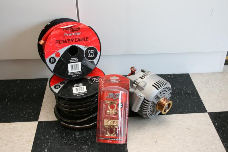
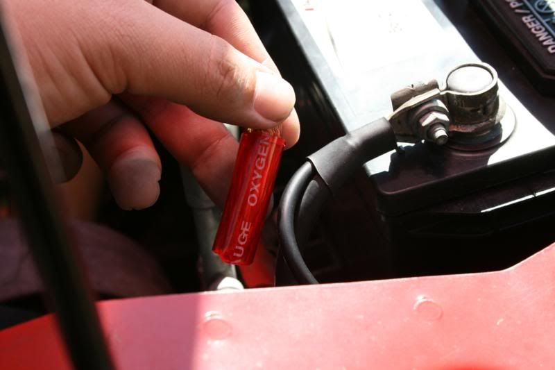
Here is what we are going to be installing. A high output alternator, Tsunami 1/0 power and ground wire, and Tsunami batter terminals. The only thing that isn't pictured is the 1/0 wire lugs and shrink wrap, both can be purchased at various hardware stores.

When upgrading power wire you always want to make sure you have good quality wire. I really like Tsunami brand products. Their wire is true to size it is supposed to be, it is high quality, and the part that I like alot is the jacket is very thick. For being 1/0 it is very flexible too, you can tie small tight knots in it with ease. This makes routing it much easier.
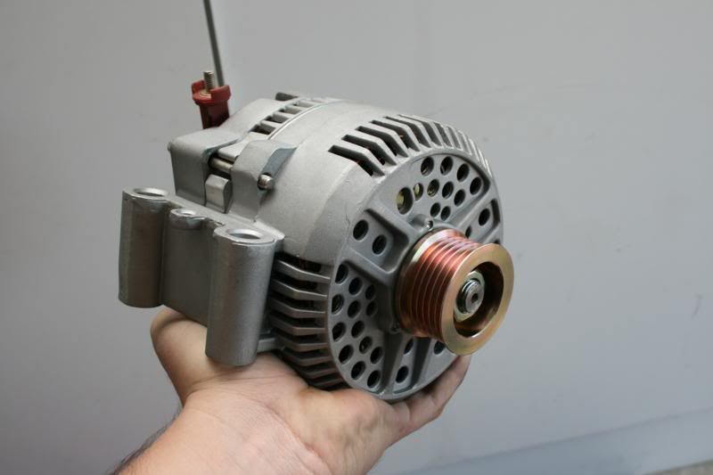
The new alternator. As stated previously this is a unit from Motor City Reman. It is 200 amp versus the factory 95 amp unit, this upgrade will make a huge difference.
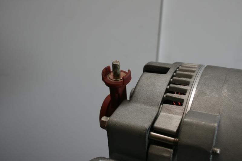
Before installing it, the little side pieces of plastic need to be trimmed off. These will get in the way of the new wire lug and are only there to hold the factory boot in place which isn't being reused anyway.
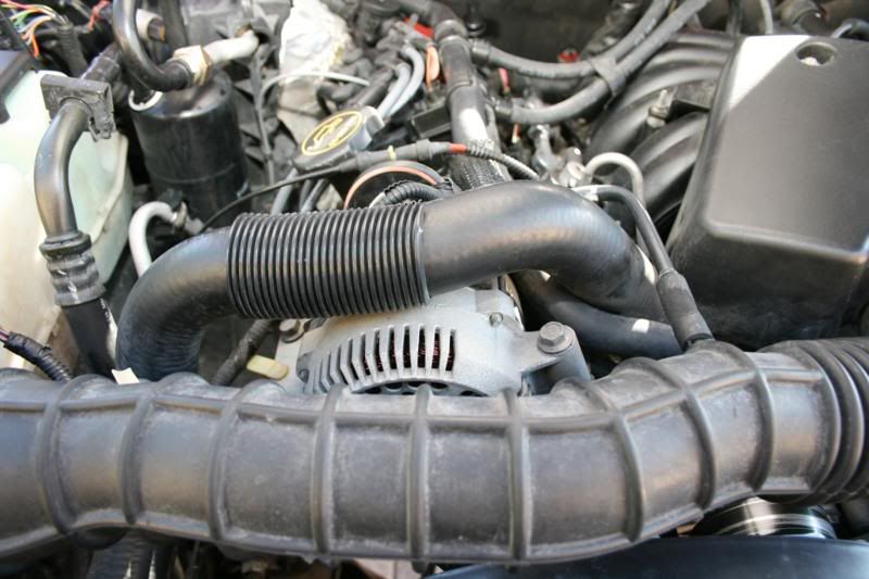
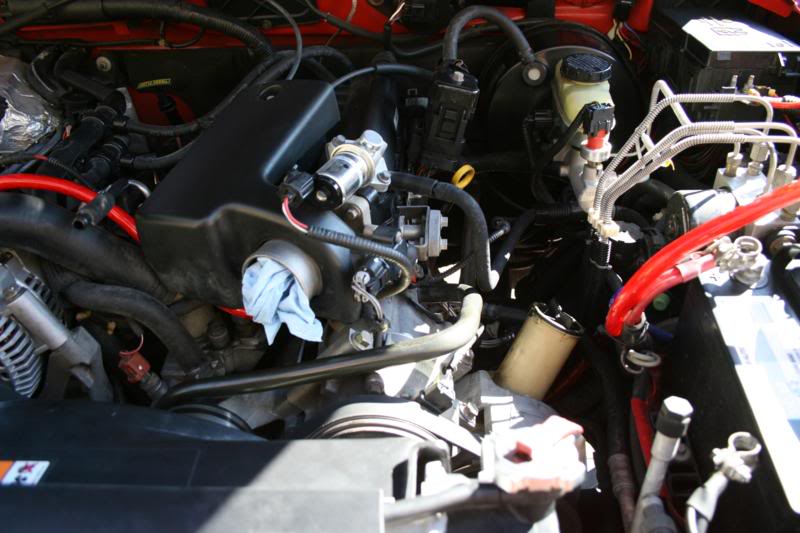
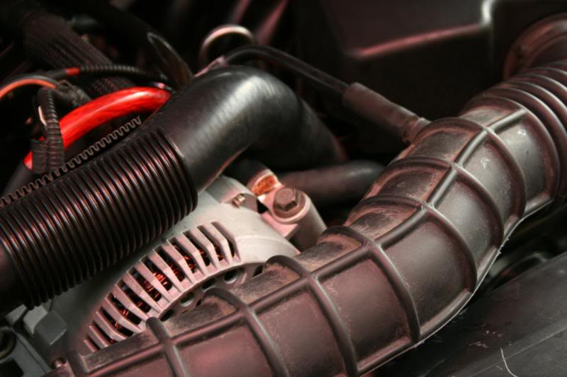
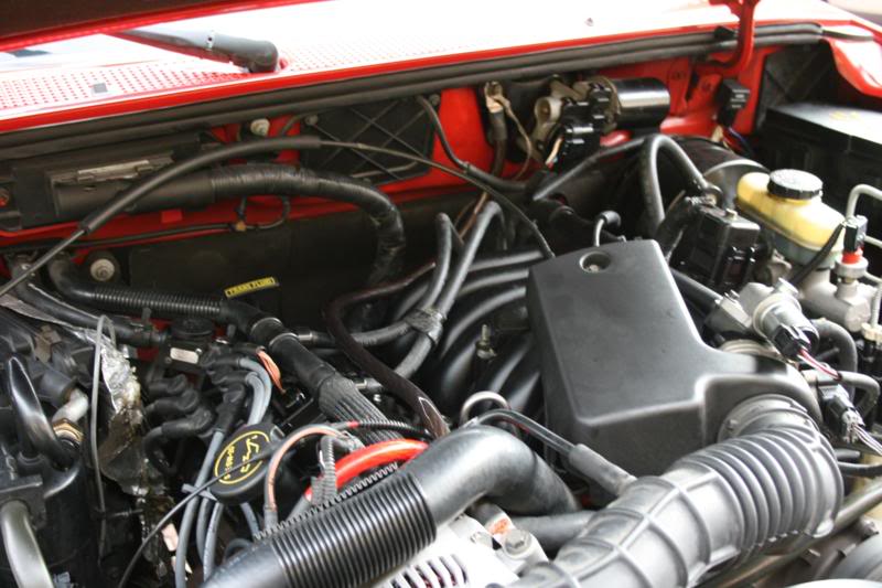
Here is the stock alternator hiding under the upper radiator hose and intake.
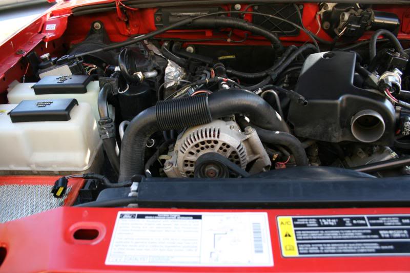
First take the intake off.
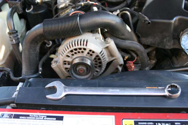
Now use a regular wrench to loosen the tensioner and take the belt off of the pulley.
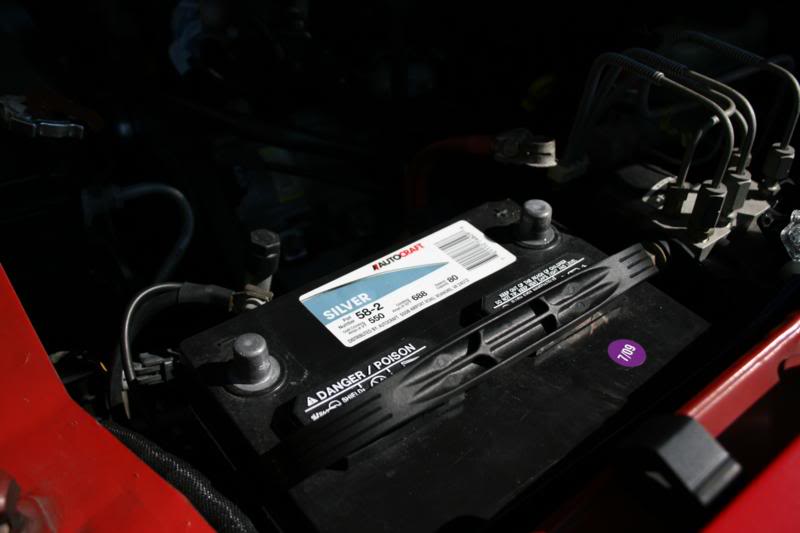
Before going further, disconnect the battery terminals.
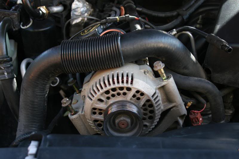
Now, the alternator is held in with 3 bolts. Remove them.
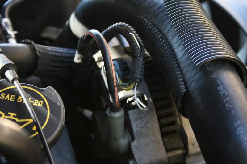
Now it is time to disconnect the alternator wires. The plugs simply unclip, and for the power wire you need to peel back the boot and there is a nut under it which you will remove. This will free the ring terminal. You can cut the boot off and discard it, it will no longer be used. Your alternator is now ready to remove.
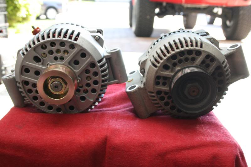
Comparing the Motor City Reman unit the the original unit you will notice a few things. The first is the new alternator is slightly larger. It also has a smaller pulley which will help give you more amps at idle, as long as your old belt isn't stretched horribly then you will not need a new one.
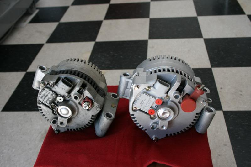
Looking at the back you will notice the stud for the power lead is also moved, this makes things easier.
Now, bolt the new unit in and then connect your wires. You also need to make a new wire out of the 1/0 to go from the stud directly to your battery terminal. If you need help figuring out how to crimp the wire lug on, refer to my Probox subwoofer or Infinity Basslink tutorials. The same method is used.
I chose to route it along the same path as the factory cable goes. The Tsunami wire made this a lot easier since it is so flexible.
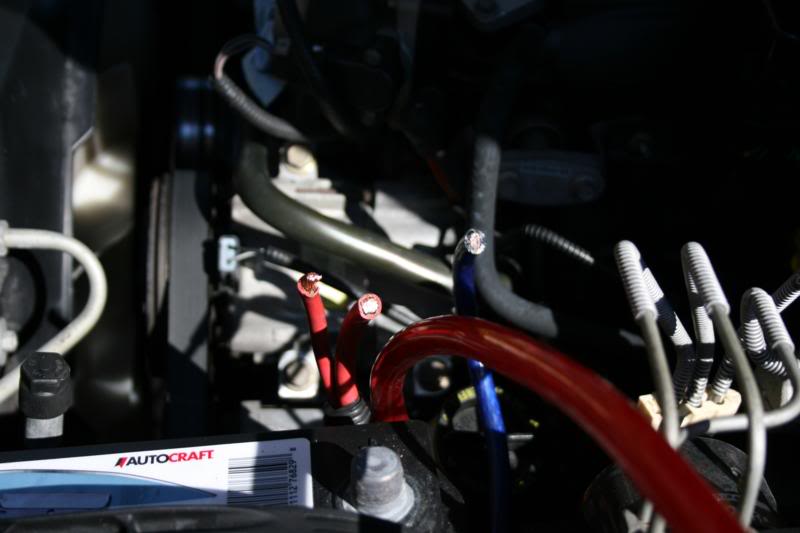
Wire coming up along with the stock wires which have already been cut from the stock terminal and stripped.
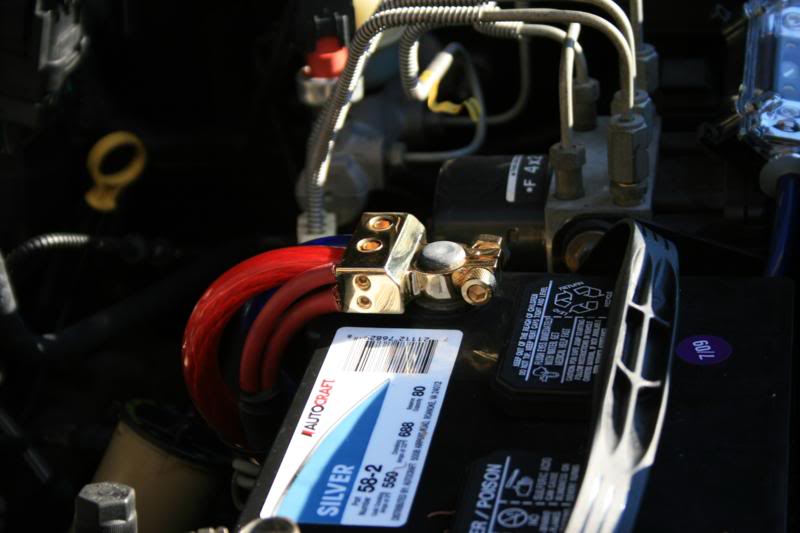
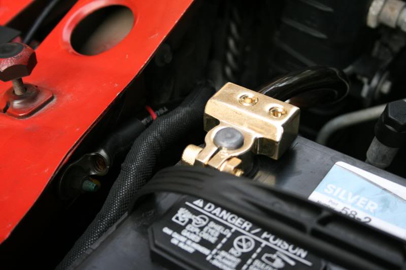
Attach to your new terminal.
Now it is time to do the ground wires.
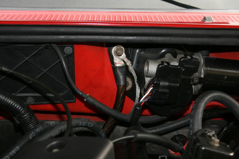
Notice how small the factory chassis ground is, especially when compared to the new 1/0.
Cut that old cable out completely and replace it with 1/0 ground wire. You can connect it to the same location or down to the vehicle frame directly, just make sure you sand the metal first.
Our last wire we need to upgrade is the engine to chassis ground. The factory ground strap bolts to the very bottom of the very back of the block and you can't get to the bolt, but will we still use the factory chassis ground location.
For the engine ground we are going to use one of the bolts that hold on the alternator. Remove the bolt and then put your wire lug there.
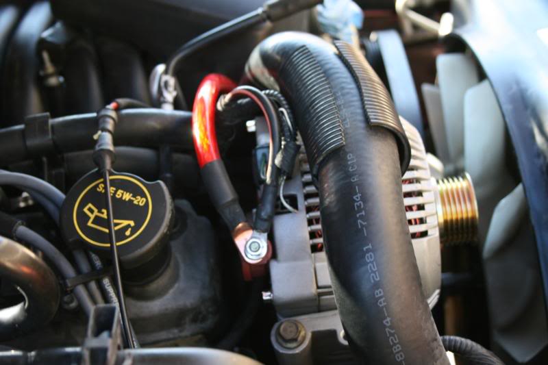
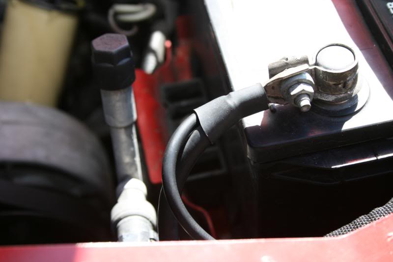
Full path of the wire. Install done!
Here is a video showing my volts after. Before the install around full volume playing this song at idle my factory volt gauge would almost go all the way down, with voltage going to just over 12 volts. Watch the video to see how it is now in the same situation, speaks for itself.
For more information on the wire and terminals I used, visit Tsunami at Tsunami: RCA Cables: X20 RCA Cables Twisted
For more information on the alternator visit Motor City Reman at
MAXX High Performance Alternators
Original thread: https://www.ranger-forums.com/f59/ho...system-102462/
Let the modding Begin!!
_________________________
A lot of people on here have a lot of extra electric accessories added to their trucks. Things like auxiliary lighting, stereo amplifiers, air compressors, etc are all items that take a lot of power to use. After finding myself needing more power I decided to upgrade my electrical system on the truck.
For this tutorial I am going to show you how to install a high output 200 amp alternator from Motor City Reman and do the "Big 3" wiring upgrade.
Here is what we are going to be installing. A high output alternator, Tsunami 1/0 power and ground wire, and Tsunami batter terminals. The only thing that isn't pictured is the 1/0 wire lugs and shrink wrap, both can be purchased at various hardware stores.
When upgrading power wire you always want to make sure you have good quality wire. I really like Tsunami brand products. Their wire is true to size it is supposed to be, it is high quality, and the part that I like alot is the jacket is very thick. For being 1/0 it is very flexible too, you can tie small tight knots in it with ease. This makes routing it much easier.
The new alternator. As stated previously this is a unit from Motor City Reman. It is 200 amp versus the factory 95 amp unit, this upgrade will make a huge difference.
Before installing it, the little side pieces of plastic need to be trimmed off. These will get in the way of the new wire lug and are only there to hold the factory boot in place which isn't being reused anyway.
Here is the stock alternator hiding under the upper radiator hose and intake.
First take the intake off.
Now use a regular wrench to loosen the tensioner and take the belt off of the pulley.
Before going further, disconnect the battery terminals.
Now, the alternator is held in with 3 bolts. Remove them.
Now it is time to disconnect the alternator wires. The plugs simply unclip, and for the power wire you need to peel back the boot and there is a nut under it which you will remove. This will free the ring terminal. You can cut the boot off and discard it, it will no longer be used. Your alternator is now ready to remove.
Comparing the Motor City Reman unit the the original unit you will notice a few things. The first is the new alternator is slightly larger. It also has a smaller pulley which will help give you more amps at idle, as long as your old belt isn't stretched horribly then you will not need a new one.
Looking at the back you will notice the stud for the power lead is also moved, this makes things easier.
Now, bolt the new unit in and then connect your wires. You also need to make a new wire out of the 1/0 to go from the stud directly to your battery terminal. If you need help figuring out how to crimp the wire lug on, refer to my Probox subwoofer or Infinity Basslink tutorials. The same method is used.
I chose to route it along the same path as the factory cable goes. The Tsunami wire made this a lot easier since it is so flexible.
Wire coming up along with the stock wires which have already been cut from the stock terminal and stripped.
Attach to your new terminal.
Now it is time to do the ground wires.
Notice how small the factory chassis ground is, especially when compared to the new 1/0.
Cut that old cable out completely and replace it with 1/0 ground wire. You can connect it to the same location or down to the vehicle frame directly, just make sure you sand the metal first.
Our last wire we need to upgrade is the engine to chassis ground. The factory ground strap bolts to the very bottom of the very back of the block and you can't get to the bolt, but will we still use the factory chassis ground location.
For the engine ground we are going to use one of the bolts that hold on the alternator. Remove the bolt and then put your wire lug there.
Full path of the wire. Install done!
Here is a video showing my volts after. Before the install around full volume playing this song at idle my factory volt gauge would almost go all the way down, with voltage going to just over 12 volts. Watch the video to see how it is now in the same situation, speaks for itself.
For more information on the wire and terminals I used, visit Tsunami at Tsunami: RCA Cables: X20 RCA Cables Twisted
For more information on the alternator visit Motor City Reman at
MAXX High Performance Alternators
Last edited by 98liftedranger; Nov 27, 2011 at 09:52 PM.

Member

Joined: Jan 2014
Posts: 1
Likes: 0
From: Hastings, NE
Thanks for the great tutorial! Quick question...when you cut out the factory ground wires from the negative terminal of the battery, did you reconnect the ground wire that connected to the left rear of the engine? It looks like you only replaced the ground wires with 1/0 ground from the battery to the chassis. Why did you decide to get rid of the old ground from the battery to the engine?


I know this is an old thread but anyone doing this mod, especially the ground wires please add the following:
These are my opinions and I believe create a better flowing ground harness.
Make sure to run a ground wire to the following Components:
1) Use an engine block bolt as a engine ground, sometimes there are extra bolt holes on the front of the engine. This allows a better for better path for all electrical components.
2) The Alternator should have a separate full size wire for a ground run back to the battery. Give the alternator a direct path back to the battery and allows for better charging.
3) Add a ground wire from the Starter Mounting Bolt to the Common ground point or directly back tot eh battery. (Add a better return path o the battery for the current, allowing the starter to receive and maintain full power starts. Reduces wear on the electrical parts.
When you allow the current to return to the battery and it has to go through multiple connections, i.e. bolts, rubber bushing, dirty connections, this reduces the current flow and does not allow each component to run at full capacity, which in turn leads to early failure.

Thread
Thread Starter
Forum
Replies
Last Post
ChristianGuy
General Ford Ranger Discussion
24
Mar 25, 2011 09:14 AM


