


2008 ranger OHC wiring help

Thread Starter
|
Member

Joined: Feb 2011
Posts: 758
Likes: 1
From: Alberta
 2008 ranger OHC wiring help
Just recieved my OHC in the mail from hooligan!!
A couple of questions from a novice ranger owner.
I have pulled up as much info on this as possible, but am now in need of clarification of where some of the wires actually are.
IIRC, the 2008s do not have a GEM module located behind the radio, and must use the SMART JUNCTION box for the grey/black wire. I have found a bunch of wires down by the e-brake pedal and located on that I think is the right wire (grey/black one).
For the Map light power, it says to use a light green and orange wire at the dimmer module. Can someone take a picture of where this module is so I may locate the wire?
There is also apparently a Console VSS wire (grey/black) at console and (purple/orange) at the Pin #1 of the center PCM connector
Now, where on earth is this center PCM connector? My best guess is that its under the hood plugged into the firewall by the passengers' side?? A diagram would also be helpful for locating Pin #1
I am going to use wire-taps for all my wiring into the stock harnesses.
I plan to make a little revised How-to for us guys who have newer rangers.
Thanks
A couple of questions from a novice ranger owner.
I have pulled up as much info on this as possible, but am now in need of clarification of where some of the wires actually are.
IIRC, the 2008s do not have a GEM module located behind the radio, and must use the SMART JUNCTION box for the grey/black wire. I have found a bunch of wires down by the e-brake pedal and located on that I think is the right wire (grey/black one).
For the Map light power, it says to use a light green and orange wire at the dimmer module. Can someone take a picture of where this module is so I may locate the wire?
There is also apparently a Console VSS wire (grey/black) at console and (purple/orange) at the Pin #1 of the center PCM connector
Now, where on earth is this center PCM connector? My best guess is that its under the hood plugged into the firewall by the passengers' side?? A diagram would also be helpful for locating Pin #1
I am going to use wire-taps for all my wiring into the stock harnesses.
I plan to make a little revised How-to for us guys who have newer rangers.
Thanks

~~~~~~~~~~~~~~~~~~~~~~~~~~~~~~~~~~~~~~~~~~~~~~
95~01 Explorer Overhead Console into a 07~10 Ranger
These two wires run directly between the overhead console and the ambient temperature sensor, completely separate from the truck harness:
These wires at the console pigtail would need to be extended and tapped into the Ranger's factory wiring:
~~~~~~~~~~~~~~~~~~~~~~~~~~~~~~~~~~~~~~~~~~~~~~~~
Important note #1:
Notice the difference between the White/Blue and the Blue/White wires in the radio harness as listed above. These are not the same and they are not interchangeable.
Important note #2:
The 2007~2010 Ranger no longer has practical way to tap into the "Battery Saver" feature for use with the Ex console map lights. So, if a map light is wired to a constant hot (Violet/Red as shown above) and it is inadvertently left on overnight, it could kill the battery. An alternative would be to wire the maps to the keyed console power (White/Blue referenced above). Of course, then the maps would only work with the key in the RUN or ACC position. It's a matter of preference.
~~~~~~~~~~~~~~~~~~~~~~~~~~~~~~~~~~~~~~~~~~~~~~~~~
Cutting headliner and installation of the console bracket:
http://www.cardomain.com/ride/296394/3
These two wires run directly between the overhead console and the ambient temperature sensor, completely separate from the truck harness:
- Console temp: Dark Blue/White ---> Temp sensor Dark Blue/White
- Console temp: Dark Blue/Yellow ---> Temp sensor Dark Blue/Yellow
These wires at the console pigtail would need to be extended and tapped into the Ranger's factory wiring:
- Console Power: Grey/Yellow ---> White/Blue (white wire with blue stripe - truck radio harness)
- Console Night Dim: Light Blue/Red or Red/Black ---> Blue/White (blue wire with white stripe - truck radio harness)
- Console Maps: Green/Orange ---> Violet/Red (truck radio harness)
- Console Dome: Black/Blue ---> Green/Blue (above truck's factory dome)
- Console VSS: Grey/Black ---> Violet/Orange (pin #1 of the truck's center PCM connector)
- Console Ground: Black ---> truck chassis ground
~~~~~~~~~~~~~~~~~~~~~~~~~~~~~~~~~~~~~~~~~~~~~~~~
Important note #1:
Notice the difference between the White/Blue and the Blue/White wires in the radio harness as listed above. These are not the same and they are not interchangeable.
- White/Blue = white wire with blue stripe
- Blue/White = blue wire with white stripe
Important note #2:
The 2007~2010 Ranger no longer has practical way to tap into the "Battery Saver" feature for use with the Ex console map lights. So, if a map light is wired to a constant hot (Violet/Red as shown above) and it is inadvertently left on overnight, it could kill the battery. An alternative would be to wire the maps to the keyed console power (White/Blue referenced above). Of course, then the maps would only work with the key in the RUN or ACC position. It's a matter of preference.
~~~~~~~~~~~~~~~~~~~~~~~~~~~~~~~~~~~~~~~~~~~~~~~~~
Cutting headliner and installation of the console bracket:
http://www.cardomain.com/ride/296394/3
Thread Starter
|
Member
Joined: Feb 2011
Posts: 758
Likes: 1
From: Alberta
Console Power: Grey/Yellow ---> White/Blue (white wire with blue stripe - truck radio harness)
Console Night Dim: Light Blue/Red or Red/Black ---> Blue/White (blue wire with white stripe - truck radio harness)
Console Maps: Green/Orange ---> Violet/Red (truck radio harness)
Console Dome: Black/Blue ---> Green/Blue (above truck's factory dome)
Console VSS: Grey/Black ---> Violet/Orange (pin #1 of the truck's center PCM connector)
Console Ground: Black ---> truck chassis ground
Console Night Dim: Light Blue/Red or Red/Black ---> Blue/White (blue wire with white stripe - truck radio harness)
Console Maps: Green/Orange ---> Violet/Red (truck radio harness)
Console Dome: Black/Blue ---> Green/Blue (above truck's factory dome)
Console VSS: Grey/Black ---> Violet/Orange (pin #1 of the truck's center PCM connector)
Console Ground: Black ---> truck chassis ground
Thanks I think this helped
No, not behind the inner fender. The wire goes to the Speed Control Servo which is mounted on the paasenger side inner fender apron near of the washer fluid reservoir.
Thread Starter
|
Member
Joined: Feb 2011
Posts: 758
Likes: 1
From: Alberta
Ok I'll try to locate the speed control servo (I think I know what you are referring to). If nothing else, I will take pictures and post them so you can help me locate them.
Also, where would you run the wires through the firewall? And I am eventually wanting to do a 3" BL and if I mount the temp sensor to the frame, I will eventually need to move it when I do the lift. what would be the best material to attach the temp sensor to the frame, keeping in mind I may need to move it later on?
Also, where would you run the wires through the firewall? And I am eventually wanting to do a 3" BL and if I mount the temp sensor to the frame, I will eventually need to move it when I do the lift. what would be the best material to attach the temp sensor to the frame, keeping in mind I may need to move it later on?
Thread Starter
|
Member
Joined: Feb 2011
Posts: 758
Likes: 1
From: Alberta
Also, would I be better off to run the map lights off of a constant hot source? If so, are the 12V cig lighters on a switch when you turn off the ignition? and would you use that source or would you tap into something else behind the radio?
The sensor should not be mounted to the frame. A good place is the front of the radiator core support near the headlight but not too close to the radiator. In that position, it should get a fresh supply of ambient temperature air while the truck is moving without being exposed to road spray, rocks, bugs.
My wires run through one of a series of grommeted holes that I drilled through the firewall. Many use an existing hole like the one for the clutch pushrod (the same hole is used for the shift cable on automatic trucks).
My wires run through one of a series of grommeted holes that I drilled through the firewall. Many use an existing hole like the one for the clutch pushrod (the same hole is used for the shift cable on automatic trucks).
The violet/red in my post above is a constant hot. Be sure to read Important Note #2. In fact, you probably should reread everything above. I seem to be repeating the same information.
Your signature says 2002 but this thread is about 2007~10 which have many wiring differences. If you're installing the console in a 2001~2003 Ranger, the best wiring and installation info is in John's how-to:
http://www.cardomain.com/ride/296394...lar-cab/page-3
http://www.cardomain.com/ride/296394...lar-cab/page-4
http://www.cardomain.com/ride/296394...lar-cab/page-3
http://www.cardomain.com/ride/296394...lar-cab/page-4
Thread Starter
|
Member
Joined: Feb 2011
Posts: 758
Likes: 1
From: Alberta
I am going to attempt this tomorrow.... Fingers crossed!!
I'm excited, but also a tad nervous. And I can't decide what part I am most uncomfortable with... Either cutting into my headliner and drilling into my roof (not too far....) or running the wires through the firewall... I will try to find spots to run them through the firewall BEFORE I cut up my headliner.
I bought some 18ga. wire and some wire-taps. The wire is all one color, so I need to create a legend as well.
As for mounting the temp sensor up by the radiator core, what do I attach it with? I have silicone and like crazy glue and stuff... I'm gonna try to pull up some pictures of where it is mounted in the exploders so I can get it as close to factory as possible (too bad, cause I had a 1996 explorer that I recently sold and I should have checked where the temp sensor was in that) :)
I'm excited, but also a tad nervous. And I can't decide what part I am most uncomfortable with... Either cutting into my headliner and drilling into my roof (not too far....) or running the wires through the firewall... I will try to find spots to run them through the firewall BEFORE I cut up my headliner.
I bought some 18ga. wire and some wire-taps. The wire is all one color, so I need to create a legend as well.
As for mounting the temp sensor up by the radiator core, what do I attach it with? I have silicone and like crazy glue and stuff... I'm gonna try to pull up some pictures of where it is mounted in the exploders so I can get it as close to factory as possible (too bad, cause I had a 1996 explorer that I recently sold and I should have checked where the temp sensor was in that) :)
Before you decide to cut into it, take a quick look at these pictures of a 2011 that were posted a couple of days ago.
https://www.ranger-forums.com/showth...light=2010+ohc
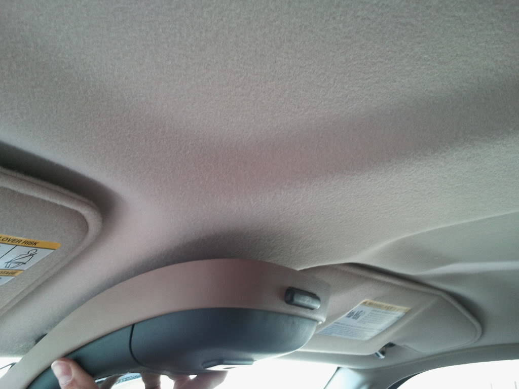
If your headliner has that shape rib running up between the visors like the 2011 pictures, you might have a difficult time getting the console to match the headliner contours. If yours looks more like the headliner in the Explorer donor, then things should go OK.
I'm not saying that it will or won't fit but if I were you, I'd spend some time researching and test fitting it before starting surgery.
https://www.ranger-forums.com/showth...light=2010+ohc
If your headliner has that shape rib running up between the visors like the 2011 pictures, you might have a difficult time getting the console to match the headliner contours. If yours looks more like the headliner in the Explorer donor, then things should go OK.
I'm not saying that it will or won't fit but if I were you, I'd spend some time researching and test fitting it before starting surgery.
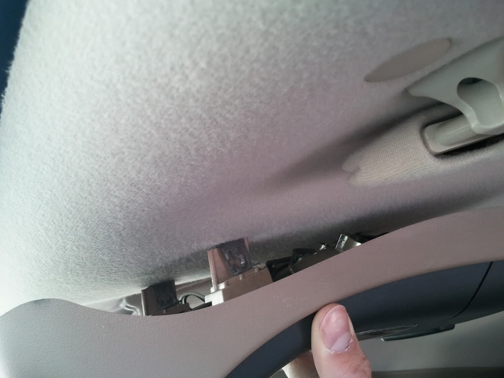
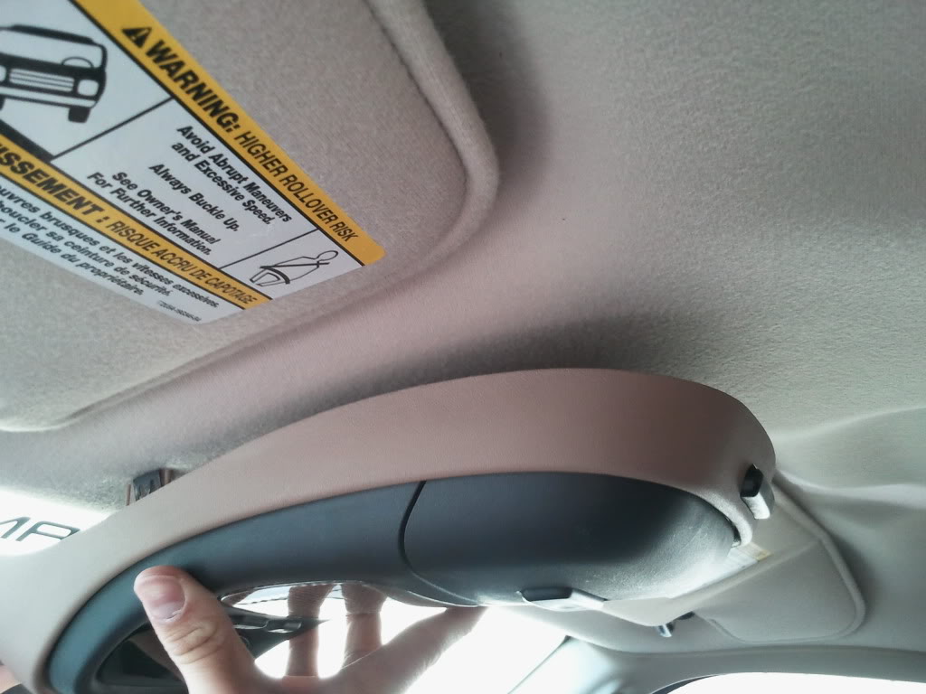
I couldn't say for sure. I THINK that your headliner is closer to my 2003 than the 2011 but It is SO hard to compare the photos.
If it looks like you can make the contour fit, then the most important question is where the sides of the console will sit compared to the width of the section between the visor indents. Is the area on the headliner wide enough and flat enough before it goes into the recesses for the visors? To my eyes, that part looks iffy in the 2011 picture. Yours looks like it might be better but I really can't tell.
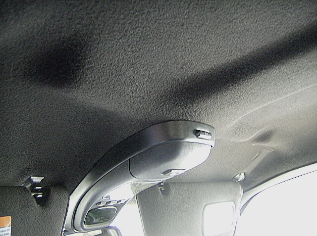
Mine fits fairly well. The only thing I had to do was shim the headliner down at the back of the console to close up the gap and keep the headliner from "floating" above the rear of the console - almost every one I've seen seems to have had this same issue. To make the shim, I used two layers of the cutout headliner scraps glued together and tucked up between the headliner and roof, just to the rear of where the console ends. It is totally undetectable when in position.
If you do decide to go ahead and cut, then start small. You can always make the cutout larger but .... you know the rest.
If it looks like you can make the contour fit, then the most important question is where the sides of the console will sit compared to the width of the section between the visor indents. Is the area on the headliner wide enough and flat enough before it goes into the recesses for the visors? To my eyes, that part looks iffy in the 2011 picture. Yours looks like it might be better but I really can't tell.
Mine fits fairly well. The only thing I had to do was shim the headliner down at the back of the console to close up the gap and keep the headliner from "floating" above the rear of the console - almost every one I've seen seems to have had this same issue. To make the shim, I used two layers of the cutout headliner scraps glued together and tucked up between the headliner and roof, just to the rear of where the console ends. It is totally undetectable when in position.
If you do decide to go ahead and cut, then start small. You can always make the cutout larger but .... you know the rest.
Thread Starter
|
Member
Joined: Feb 2011
Posts: 758
Likes: 1
From: Alberta
Ya my headliner looks like it is a lot closer to yours than the 2011
The gaps in the indents for the visors are going to be very small (the center part seems to be wide enough to accomodate it)
I will keep in mind the shim that you made (sounds like its and easy thing to do)
The gaps in the indents for the visors are going to be very small (the center part seems to be wide enough to accomodate it)
I will keep in mind the shim that you made (sounds like its and easy thing to do)
Thread Starter
|
Member
Joined: Feb 2011
Posts: 758
Likes: 1
From: Alberta
Well I was about to cut into my headliner, and then got to thinking about how I was going to route the 3 wires through the firewall...
The firewall seems like its sealed pretty good... I have taken some pictures of the firewall by the clutch pedal (where apparently some people have routed wires) and want your opinions on where I should route them. I am at a loss as to where to look for the "other side" of the firewall and where the wires will "come out"
Do I cut into the seal where the linkage is??
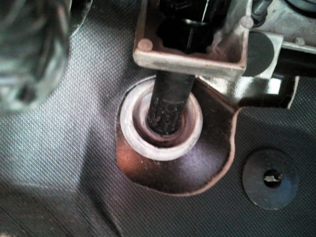
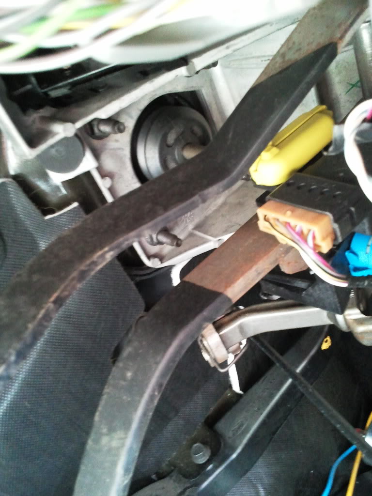
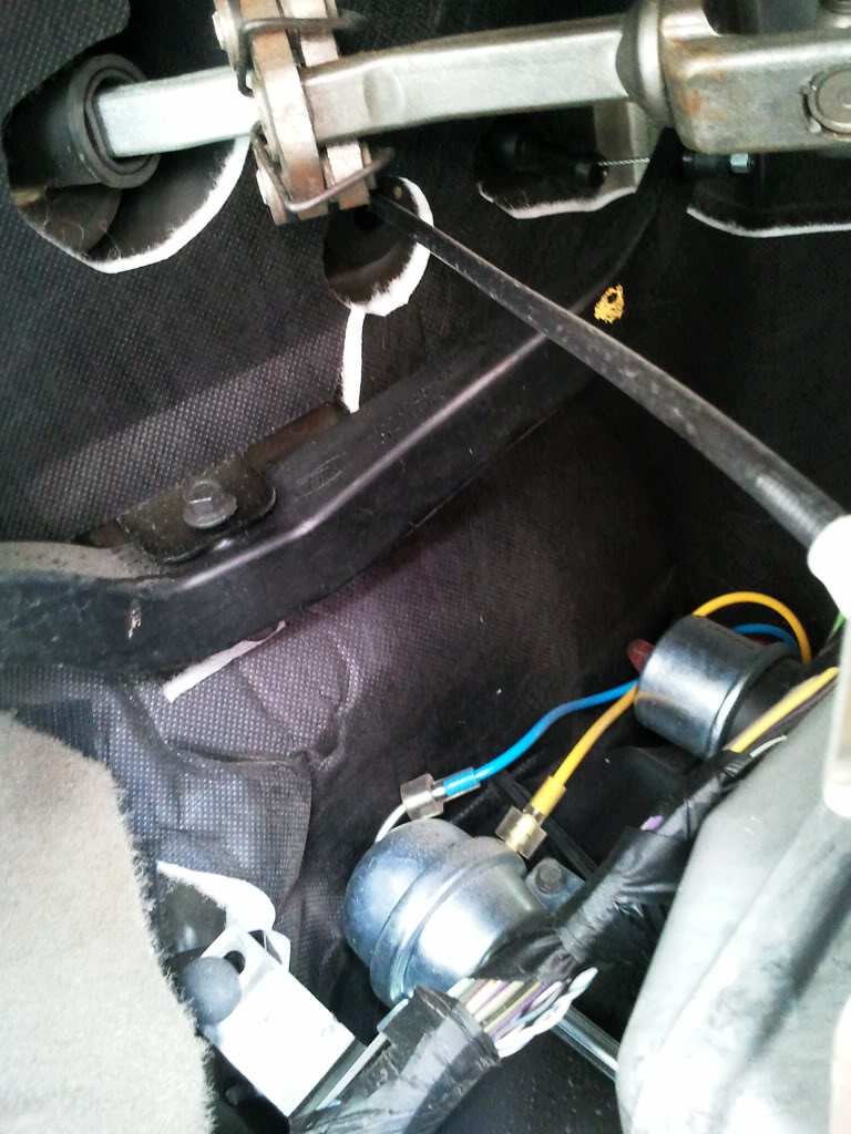
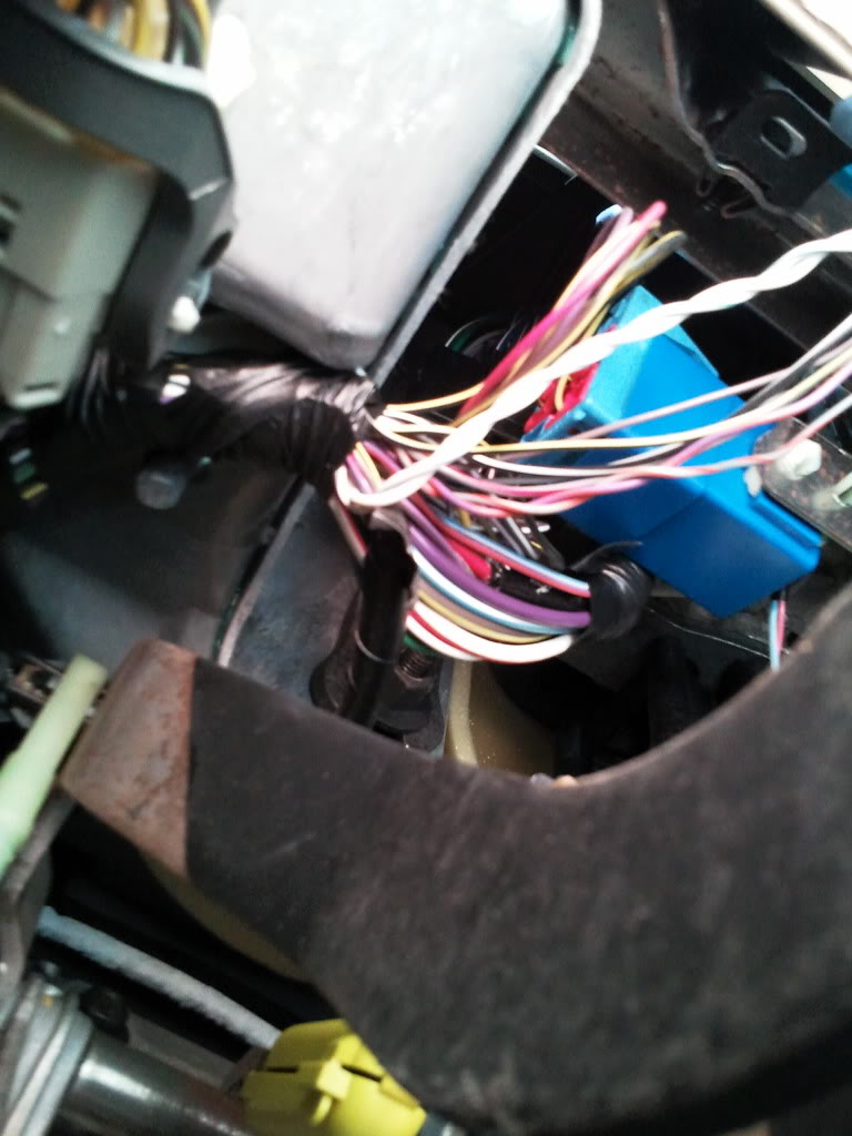
The firewall seems like its sealed pretty good... I have taken some pictures of the firewall by the clutch pedal (where apparently some people have routed wires) and want your opinions on where I should route them. I am at a loss as to where to look for the "other side" of the firewall and where the wires will "come out"
Do I cut into the seal where the linkage is??
Member
Joined: Aug 2006
Posts: 151
Likes: 0
From: SAN ANTONIO
The grey/black VSS does not exist in the 2007+ Ranger. The color code for 2007+ is violet w/orange stripe and it runs only under the hood between the PCM plug and the Speed Control Servo.
The PCM is in the PS firewall and has 3 connectors. The center connector contains the VT/OR wire. The #1 pin location is almost always marked on the connector shell with an embossed "1" if you want to bother looking for it. The alternative is to simply find the color code. If it would be easier, the other end of the same VT/OR wire can be found at the Speed Control Servo on the PS inner fender behind the washer fluid reservoir.There are only about 8 wires to deal with at the servo.
Forget about finding the LG/OR in the truck harness - that is for 2006 and earlier. See quote below.
~~~~~~~~~~~~~~~~~~~~~~~~~~~~~~~~~~~~~~~~~~~~~~
The above is from a post I put together awhile back for the 2007+ Rangers. I haven't used this info myself for a late model install, so take it for what it's worth – one possible solution based only on the schematics and nothing more.
The PCM is in the PS firewall and has 3 connectors. The center connector contains the VT/OR wire. The #1 pin location is almost always marked on the connector shell with an embossed "1" if you want to bother looking for it. The alternative is to simply find the color code. If it would be easier, the other end of the same VT/OR wire can be found at the Speed Control Servo on the PS inner fender behind the washer fluid reservoir.There are only about 8 wires to deal with at the servo.
Forget about finding the LG/OR in the truck harness - that is for 2006 and earlier. See quote below.
~~~~~~~~~~~~~~~~~~~~~~~~~~~~~~~~~~~~~~~~~~~~~~
The above is from a post I put together awhile back for the 2007+ Rangers. I haven't used this info myself for a late model install, so take it for what it's worth – one possible solution based only on the schematics and nothing more.

Thread
Thread Starter
Forum
Replies
Last Post
94greenmachine
General Ford Ranger Discussion
4
Jan 16, 2009 09:18 PM


