Coil-over sadness/madness
#201
 02-05-2011


Join Date: Feb 2010
Location: Vancouver island B.C.
Posts: 225
Likes: 0
Received 0 Likes
on
0 Posts
#202
02-23-2011


Took a little longer than expected...sorry guys!
#203
02-24-2011

#204
02-24-2011
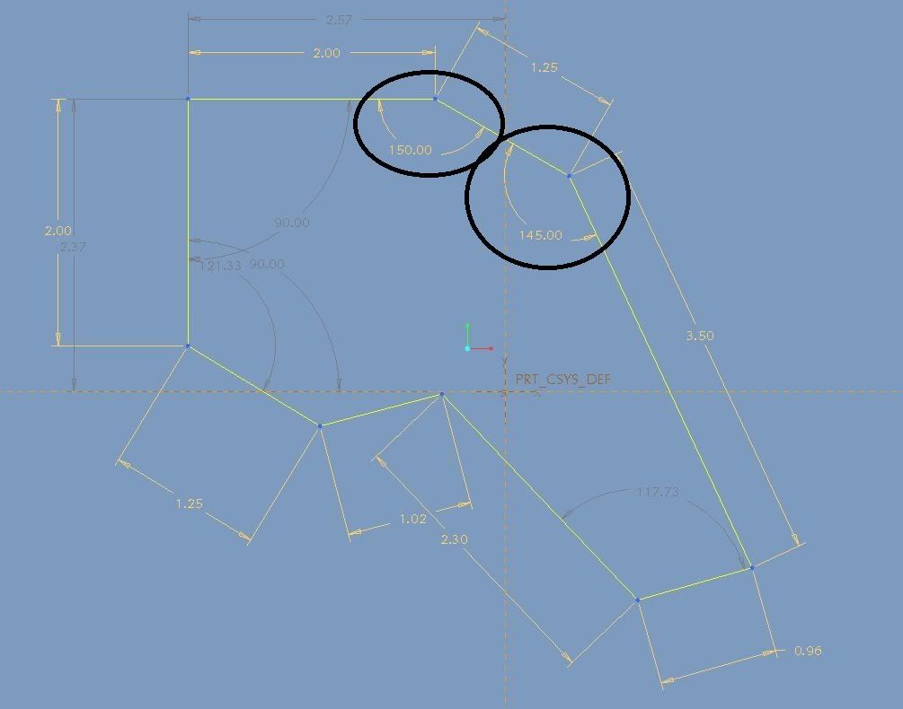
Had some time avoiding homework so I slapped these together.
The only thing they are really missing is hole locations, if somebody can get me distances for each of the holes from the 2 closest edges I can fully define these and get blue prints out. also are the ORW ones 3/16 or 1/4in steel? I might mock up a set over spring break and see how they fit.
The only thing they are really missing is hole locations, if somebody can get me distances for each of the holes from the 2 closest edges I can fully define these and get blue prints out. also are the ORW ones 3/16 or 1/4in steel? I might mock up a set over spring break and see how they fit.
#205
02-25-2011
Thanks a lot for that info I will put it into my drawings. Mikerider, looks pretty good-is that solidworks?
On hole dimensions: for proper hole dimensions someone would need to take angles and measurements of every side/piece of the brackets. If someone was willing to do this either mikerider or myself seem to have to tools to make fully dimensioned parts. Would be really cool to have a set of prints anyone could use.
I am still going to try to get a FULL part and material list together with the prints. The more info and input from others I get the better it's going to turn out. Thanks for all the help everyone
#206
02-25-2011
The only essential info I need to get a full blue print is the positions of the 2 pre existing holes on the a arm for the lower bracket and the angle between the shock mounting tabs and the rest of the bracket so they line up correctly. The rest dosen't really mater as long at the dimensions are close.
#207
02-25-2011
One of the dimensions thats is absolutely necessary for bracket construction is the tabs on the lower bracket. Not just the distance between, but the correct placement for the coilover to line up with the upper bracket. I am not sure if this is best left to be "welded into place" or if it can be welded in ahead of time. ORW must have quit making these for some reason, whether they didn't fit all vehicles or some other problem...
Edit: What I mean by placement of the tabs is the angle of the tabs to the a-arm side of the bracket.
Edit: What I mean by placement of the tabs is the angle of the tabs to the a-arm side of the bracket.
#208
02-25-2011
Thanks again logan03CO, if you have your brackets just laying around and don't mind taking a few dimensions, could you help me out with my incorrect dimensions? just to the 1/8" should be fine.
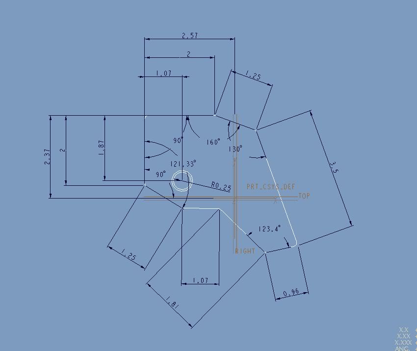
Ok the 2.37 and 2.57 are not necessary dimensions, disregard them, they are just positioning the drawing on the screen. All of the other dimensions I just made up to look like what they should. If someone could grab all the angles it would clear everything up, thanks.
Ok the 2.37 and 2.57 are not necessary dimensions, disregard them, they are just positioning the drawing on the screen. All of the other dimensions I just made up to look like what they should. If someone could grab all the angles it would clear everything up, thanks.
Last edited by ridin434; 02-25-2011 at 02:41 PM.
The following users liked this post:
Morgy23410 (02-07-2024)
#209
02-25-2011
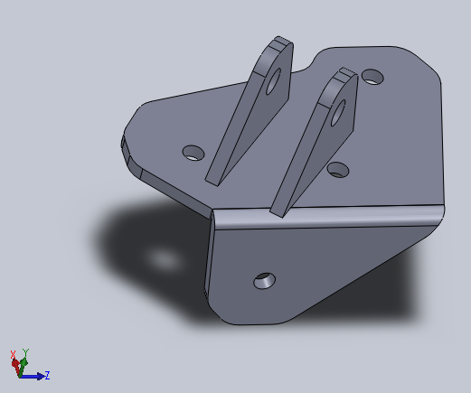
Yeah I can verify a few of them...problem is my brackets are not shaped exactly like what you have drawn. The outer perimeter is very similiar but some parts of my bracket are curved (along the lines of what mikerider posted) instead of the way you have them drawn.
It's not the best angle to show it, but it's the only ones I have on hand:


EDIT: Maybe I will just try to trace the upper brackets onto graph paper for you guys this weekend. I won't be able to finish the drawing until Monday...but I'll make sure to have a 1" scale bar on the drawing so you will know if it's really still "to-scale" after you print it out.
EDIT to the EDIT: Cancel that tracing idea.....
It's not the best angle to show it, but it's the only ones I have on hand:
EDIT: Maybe I will just try to trace the upper brackets onto graph paper for you guys this weekend. I won't be able to finish the drawing until Monday...but I'll make sure to have a 1" scale bar on the drawing so you will know if it's really still "to-scale" after you print it out.
EDIT to the EDIT: Cancel that tracing idea.....
Last edited by logan03CO; 02-25-2011 at 03:38 PM.
#210
02-25-2011
Yeah I can verify a few of them...problem is my brackets are not shaped exactly like what you have drawn. The outer perimeter is very similiar but some parts of my bracket are curved (along the lines of what mikerider posted) instead of the way you have them drawn.
It's not the best angle to show it, but it's the only ones I have on hand:
EDIT: Maybe I will just try to trace the upper brackets onto graph paper for you guys this weekend. I won't be able to finish the drawing until Monday...but I'll make sure to have a 1" scale bar on the drawing so you will know if it's really still "to-scale" after you print it out.
The upper mounts shape shouldn't matter much, as long as the dimensions clear the coilover and locate the top hole correctly in the coil bucket for aduguate load distribution and strength. The biggest thing is going to be getting the lower coil over mounts located correctly on the lower bracket so there are no clearance issues with the upper control arm and brake caliper.
anybody happen to have a CAD model of the Ranger front suspension kicking around lol.
#211
02-25-2011
I won't mess with making a drawing of my exact ones since you guys have a workable design on the uppers already rolling.
Last edited by logan03CO; 02-25-2011 at 03:34 PM.
#212
02-25-2011
Yeah I know the shapes being different won't matter on the actual install...but I won't be able to use mine as a template to verify anything else since they are constructed differently.
I won't mess with making a drawing of my exact ones since you guys have a workable design on the uppers already rolling. I wish I could help you out with the bottom mounts though.
I won't mess with making a drawing of my exact ones since you guys have a workable design on the uppers already rolling. I wish I could help you out with the bottom mounts though.
If it warms up a little next week I am going to make a template of my truck and see about getting the holes in the right spot, from there I can adjust the lower coilover mounts from there.
#213
02-25-2011
If someone has a lower bracket off and could take measurements that would be great. I am just trying to get all info on upper mount then will start on lower.
The position of the lower bracket on the A-arm is very important, no only for clearance, but keeping the angle of the coil over the same on both sides. Different angles on each side would make the load on each side different.
I suppose if you were within a half an inch on each side you would never notice though.
#214
02-25-2011
If someone has a lower bracket off and could take measurements that would be great. I am just trying to get all info on upper mount then will start on lower.
The position of the lower bracket on the A-arm is very important, no only for clearance, but keeping the angle of the coil over the same on both sides. Different angles on each side would make the load on each side different.
I suppose if you were within a half an inch on each side you would never notice though.
The position of the lower bracket on the A-arm is very important, no only for clearance, but keeping the angle of the coil over the same on both sides. Different angles on each side would make the load on each side different.
I suppose if you were within a half an inch on each side you would never notice though.
#215
02-25-2011
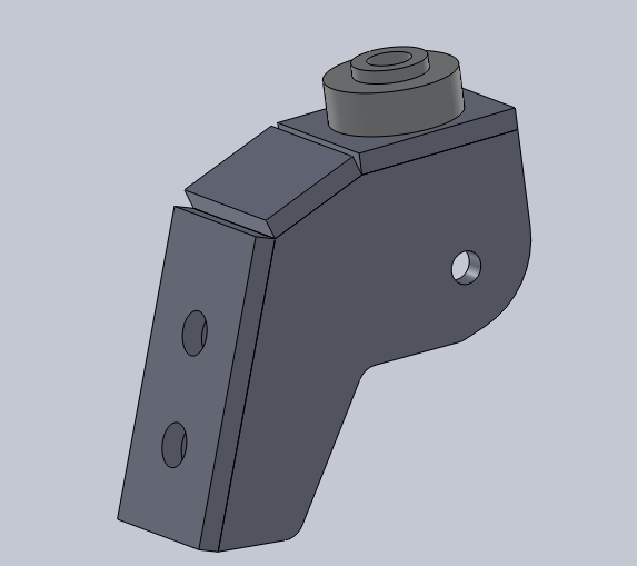
I will try to put together pictures of the lower bracket with "measurable" items... Trust me just drawing the prototype model was difficult as the bracket is angled, mounted at an angle, with angled tabs, attatching to an angled piece. My computer did not like trying to define all of that in space.
Anyone want to send me an A-arm from a ranger? haha
Anyone want to send me an A-arm from a ranger? haha
#216
02-25-2011
I will try to put together pictures of the lower bracket with "measurable" items... Trust me just drawing the prototype model was difficult as the bracket is angled, mounted at an angle, with angled tabs, attatching to an angled piece. My computer did not like trying to define all of that in space.
Anyone want to send me an A-arm from a ranger? haha
Anyone want to send me an A-arm from a ranger? haha
#217
02-25-2011
You just have to define based off of planes and reference to other lines, which is slightly trickier with pro E but doable. The hole pattern is the only essential part that needs to be defined in the part they are the reference point from the a arm to where the shock mount tabs need to be which in turn locate the coilover.
I know I am asking everyone a lot, but it is cold as hell here and I'm not at my dad's shop to be taking things apart and doing my own measurements.
Thanks everyone for the help.
Mark
#218
02-25-2011
Thats what I had to do. The only part of the lower bracket that is unknown is the hole placement, and the angle of the shock tab mounts in comparison to the bracket... I still am going to try to get a measurable picture, to attempt to get this.
I know I am asking everyone a lot, but it is cold as hell here and I'm not at my dad's shop to be taking things apart and doing my own measurements.
Thanks everyone for the help.
Mark
I know I am asking everyone a lot, but it is cold as hell here and I'm not at my dad's shop to be taking things apart and doing my own measurements.
Thanks everyone for the help.
Mark
#220
02-25-2011


#222
02-25-2011
#223
02-25-2011
Switching gears a little...
Coilover Spacers (Qty of 8 Required - Part #FOX-213-18-005-B):
A quantity of eight will come standard with the pair of Fox coilovers to go on either side of the actual coilover between the mounts.
Sample Installed Location (Top & Bottom Similar):

Close-Up:

Quantity of 8 needed:

Dimensions:

Coilover Spacers (Qty of 8 Required - Part #FOX-213-18-005-B):
A quantity of eight will come standard with the pair of Fox coilovers to go on either side of the actual coilover between the mounts.
Sample Installed Location (Top & Bottom Similar):
Close-Up:
Quantity of 8 needed:
Dimensions:
Last edited by logan03CO; 02-25-2011 at 09:22 PM.
The following users liked this post:
Morgy23410 (02-07-2024)
#225
02-26-2011
EDIT: I bet there is another hosting site that we could put the PDF's directly onto to make sure scale and everything stays correct.
Last edited by logan03CO; 02-26-2011 at 07:59 AM.


