
Not Ranger related but still for a Ford...

Thread Starter
|
Member

Joined: Jul 2005
Posts: 193
Likes: 0
From: El Paso, Texas
Not Ranger related but still for a Ford...
Rather than dish out $300-$500 for an export brace and monte carlo bar to stiffen up the front end of my 65 Mustang, I decided to make my own for under $200.
WARNING: No fancy, super light weight, "trick" billet aluminum, or CNC or laser cut parts here folks.
Made some cardboard templates and dropped them off at a friend's shop so that he could cut them for me with his plasma cutter. The goal was to make brackets that were not too over the top in design and allowed me to mount both the export brace links and monte carlo bar to the shock towers.
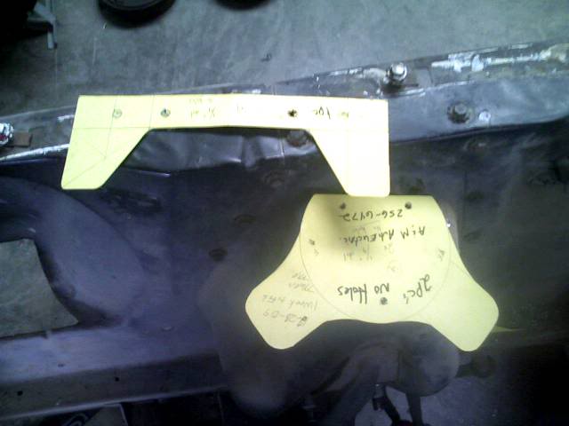
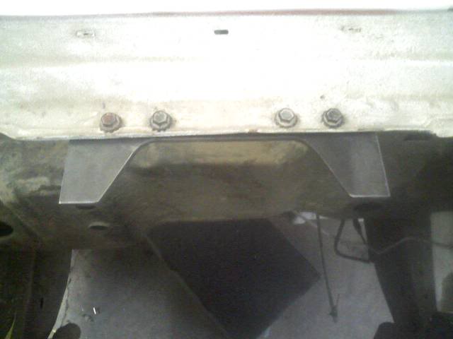
I measured the length between the firewall mounting holes and added a couple of inches to each side. I believe the final length was 12" and made two tabs for the rod ends to mount to.
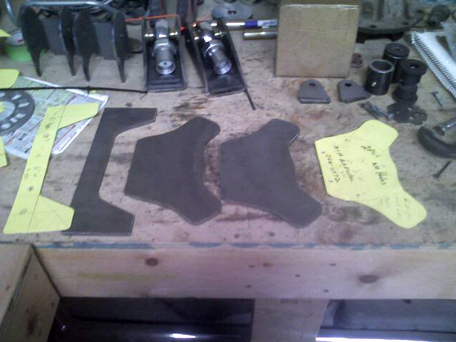
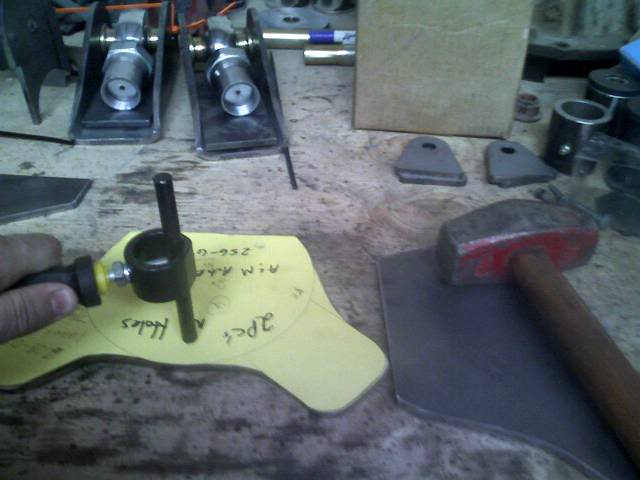
I started with a circle for the shock tower bracket then added tabs for the export links and monte carlo links. This is what I ended up with.
Had a friend trace these onto some 1/4" steel plate and cut them out with his plasma cutter. I forgot to tell him to cut out the holes for the shocks so I will have to take them back later for that.
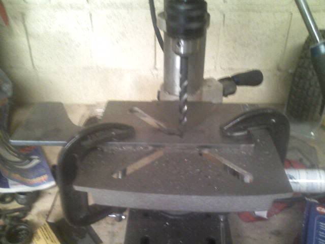
I chose to drill the holes myself one by one to ensure they would all line up. Started out with one hole from the template and used a transfer punch to mark it for the drill press.
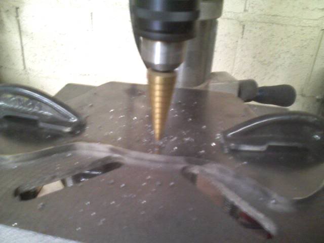
I started out with a step drill and drilled up to 1/4" diameter hole then changed out to a 5/16" drill to a 3/8" drill.
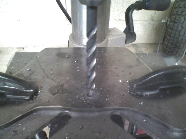
I used the shock tower caps to locate the other holes but dropping a 3/8" bolt in the previously drilled hole and once again using a transfer punch to mark the next hole and after drilling the second hole, repeated the process again to mark the third hole.
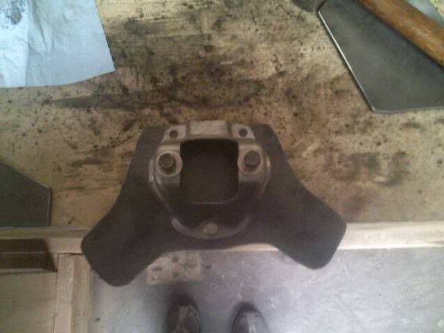
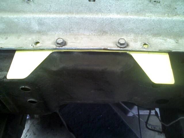
Using a similar process as the shock tower brackets, I drilled one hole at a time on the firewall bracket, mounted it, marked the next hole, drilled it, re-mounted, etc.
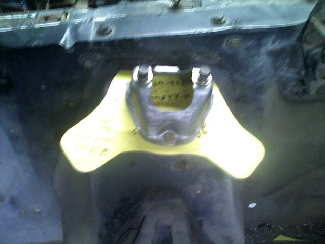
Mounted up the shock tower bracket as well to start taking measurements and deciding where to drill holes for the rod ends.
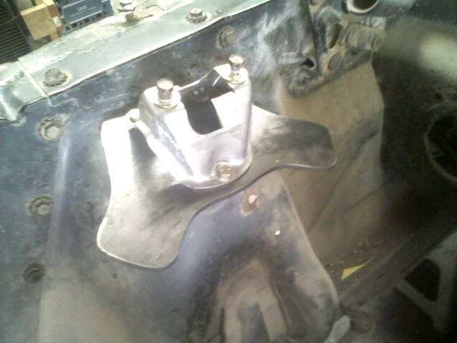
After deciding where to drill holes for the rod ends, I drilled them going from a step drill to 5/16" to 3/8" to 1/2" and finally to 5/8" which is a very expensive drill bit.
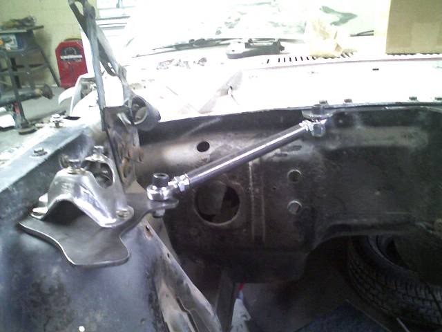
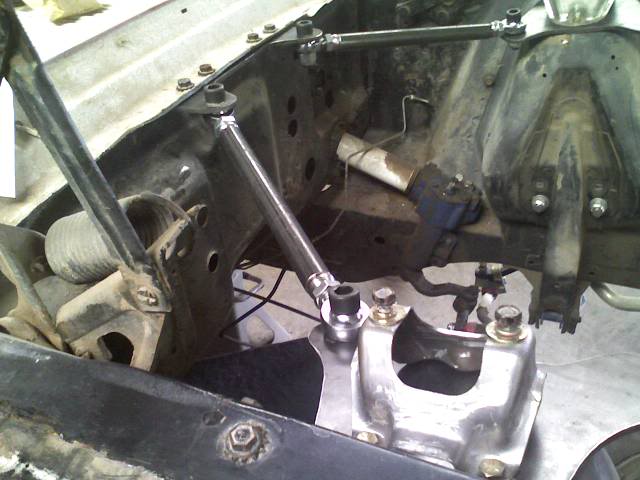
I mounted up the rod ends and took measurements between the tube adapters and decided on a 10.5" length tube.
Used some scrap tubing I had laying around to mock stuff up before I cut up some perfectly good mild steel.
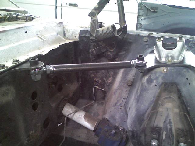
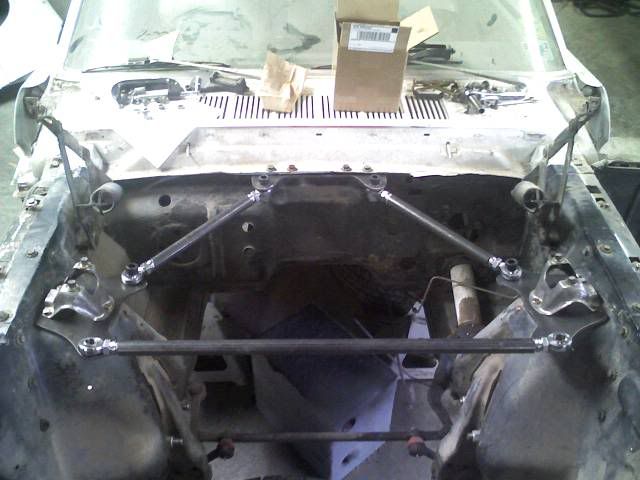
First I used some spare hardware I had laying around to mock up the first link. Then I decided that looking for matching spare hardware in a "box-o-****" is a pain in the ***, I took my *** down to the hardware store and picked up some 5/8" hardware. Allen head bolts and nylon locking nuts.
Then the other side
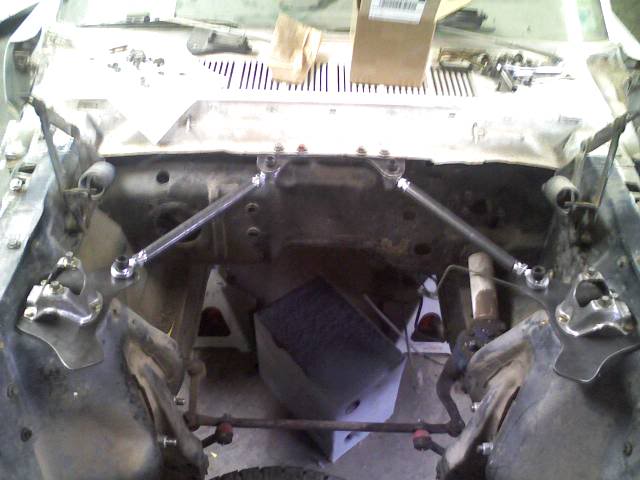
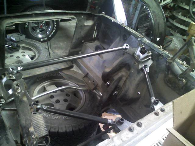
Both. I do have some contact between the rod ends and the brackets because the misalignment is a little too much but some tapered cone steel spacers should take care of this problem very easily. On order.
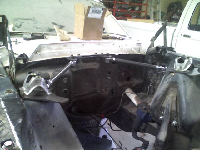
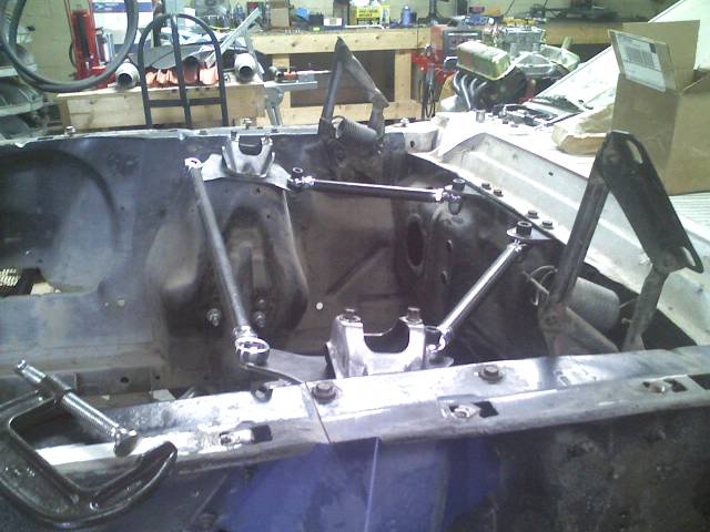
Since I have not drilled holes yet for the monte carlo bar, I used c-clamps top hold the rod ends in place and took a measurement: 27". Cut it and mocked it up. Won't be bolting it in until the motor goes in to make sure I clear the distributor.
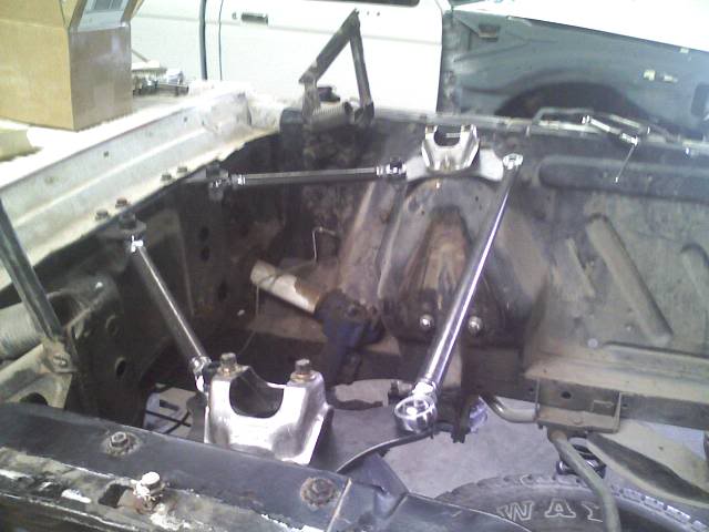
I'm waiting on some tapered cone spacers to give me higher misalignment for better clearances between the rod ends and brackets.
Fred
WARNING: No fancy, super light weight, "trick" billet aluminum, or CNC or laser cut parts here folks.
Made some cardboard templates and dropped them off at a friend's shop so that he could cut them for me with his plasma cutter. The goal was to make brackets that were not too over the top in design and allowed me to mount both the export brace links and monte carlo bar to the shock towers.
I measured the length between the firewall mounting holes and added a couple of inches to each side. I believe the final length was 12" and made two tabs for the rod ends to mount to.
I started with a circle for the shock tower bracket then added tabs for the export links and monte carlo links. This is what I ended up with.
Had a friend trace these onto some 1/4" steel plate and cut them out with his plasma cutter. I forgot to tell him to cut out the holes for the shocks so I will have to take them back later for that.
I chose to drill the holes myself one by one to ensure they would all line up. Started out with one hole from the template and used a transfer punch to mark it for the drill press.
I started out with a step drill and drilled up to 1/4" diameter hole then changed out to a 5/16" drill to a 3/8" drill.
I used the shock tower caps to locate the other holes but dropping a 3/8" bolt in the previously drilled hole and once again using a transfer punch to mark the next hole and after drilling the second hole, repeated the process again to mark the third hole.
Using a similar process as the shock tower brackets, I drilled one hole at a time on the firewall bracket, mounted it, marked the next hole, drilled it, re-mounted, etc.
Mounted up the shock tower bracket as well to start taking measurements and deciding where to drill holes for the rod ends.
After deciding where to drill holes for the rod ends, I drilled them going from a step drill to 5/16" to 3/8" to 1/2" and finally to 5/8" which is a very expensive drill bit.
I mounted up the rod ends and took measurements between the tube adapters and decided on a 10.5" length tube.
Used some scrap tubing I had laying around to mock stuff up before I cut up some perfectly good mild steel.
First I used some spare hardware I had laying around to mock up the first link. Then I decided that looking for matching spare hardware in a "box-o-****" is a pain in the ***, I took my *** down to the hardware store and picked up some 5/8" hardware. Allen head bolts and nylon locking nuts.
Then the other side
Both. I do have some contact between the rod ends and the brackets because the misalignment is a little too much but some tapered cone steel spacers should take care of this problem very easily. On order.
Since I have not drilled holes yet for the monte carlo bar, I used c-clamps top hold the rod ends in place and took a measurement: 27". Cut it and mocked it up. Won't be bolting it in until the motor goes in to make sure I clear the distributor.
I'm waiting on some tapered cone spacers to give me higher misalignment for better clearances between the rod ends and brackets.
Fred


Thread
Thread Starter
Forum
Replies
Last Post
tde720
General Technical & Electrical
4
Oct 7, 2014 04:00 PM
Rick-RF
General Ford Ranger Discussion
23
Jan 20, 2010 06:10 PM
buggman
General Technical & Electrical
1
Nov 19, 2008 11:00 AM


