
Cam synchronizer replacement

Thread Starter
|
Member
Joined: Dec 2014
Posts: 427
Likes: 25
From: Peoria
Cam synchronizer replacement
My cam synchro has been squeaking lately...
When I go to replace it, do I need the alignment tool or can I just drop in the new one in the exact same position as the old syncro?
When I go to replace it, do I need the alignment tool or can I just drop in the new one in the exact same position as the old syncro?


You should use alignment tool, but you can certainly mark where rotor position is and then install new one to match that position.
remember drive gear is angled so rotor turns a bit when lowered into hole
remember drive gear is angled so rotor turns a bit when lowered into hole
Step on and Step off pertain to the type of wire connector, Ford changed it but not sure when.
Call a Ford parts dealer with your VIN, and get part number for your VIN, then you can cross reference it.
I think a Step off(without step) connector will work with both step on and step off.......I think.
If you want to check it yourself pull of the connector and look at the sensor end(female), the step off will be the same size all the way front to back.
Step on will be smaller towards the back
Cam sensor also come in 2 wire and 3 wire versions, you need to make sure replacement matches your harness, 2 or 3 wires, they are not interchangeable
Last edited by RonD; Nov 21, 2015 at 10:08 AM.
You will need to get a new bolt, lol.
To get the rounded one out you will need a "grip-bolt" type socket
Google: grip bolt extractor
Or damaged bolt remover
They basically dig into rounded head when turned counter-clockwise(loosening bolt), you often tap them in place with hammer to get better grip
You can also get similar design but instead of socket wrench you can use an open end or box wrench on it.
Thread Starter
|
Member
Joined: Dec 2014
Posts: 427
Likes: 25
From: Peoria
i got the bolt out, swaped in the new synch. engine runs. and no oil leaks. how do i know if i did it EXACTLY right? i didn't use the alignment tool, just marked locations and lined em up. i have oil pressure. how do i know using a scan tool if the alignment is safe?
Thread Starter
|
Member
Joined: Dec 2014
Posts: 427
Likes: 25
From: Peoria
also, why does my scan tool always show SHTFT11 as a small fluctuating percentage (short term fuel trim bank 1) but shtft12 is always maxed at 99 percent? i have new o2 sensors and iacv. idk what to do. my fuel mileage is always roughly 20mpg city/highway.
Thread Starter
|
Member
Joined: Dec 2014
Posts: 427
Likes: 25
From: Peoria
Apparantly theres a difference between STFT and SHTFT
STFT = short term fuel trim bank 1
SHTFT = short term fuel trim bank 1 sensor 1
Why is mine maxed out? and also even with new o2 sensors only one engine bank goes into closed loop operation.
STFT = short term fuel trim bank 1
SHTFT = short term fuel trim bank 1 sensor 1
Why is mine maxed out? and also even with new o2 sensors only one engine bank goes into closed loop operation.
Never read SHTFT ??
STFT 1
STFT 2
Is all there is on a V engine, 2 banks
These are dwell time(open time) for fuel injectors
There is LTFT(long term fuel trim) that is just used when engine is in open loop, but is based on averages STFTs
What brand of scanner is it?
As far as I know the computer is in Open Loop or Closed Loop, one bank not working would put computer in Open Loop not just that bank
And CEL would be on if O2 sensor wasn't working
Thread Starter
|
Member
Joined: Dec 2014
Posts: 427
Likes: 25
From: Peoria
I worked that issue out. I will do further research.
I wanna know if i did the synch right though.
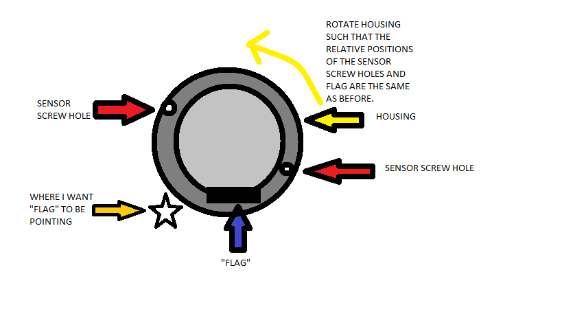
I made sure the relative position between the sensor and the "flag" was exactly the same as before, using reason I figured that the orientation of the HOUSING was not important as long as the sensor is reading the same position as before.... in other words, if I was off a tooth, rotate the HOUSING, not the gear (so I don't have to remove it again) so that the flag aligns with the mark i put on the new housing correlating to the old mark on the old synchro. In other words, the entire assembly is oriented about 30 degrees clockwise from where it used to be in order to make sure the flag is in the same spot in relation to the sensor magnet.
Is this okay? Ive driven around town with no strange noises, no lack of power, spark advance/retard (read from scanner) seems to operate as before, no CELS, still have oil pressure.
I wanna know if i did the synch right though.
I made sure the relative position between the sensor and the "flag" was exactly the same as before, using reason I figured that the orientation of the HOUSING was not important as long as the sensor is reading the same position as before.... in other words, if I was off a tooth, rotate the HOUSING, not the gear (so I don't have to remove it again) so that the flag aligns with the mark i put on the new housing correlating to the old mark on the old synchro. In other words, the entire assembly is oriented about 30 degrees clockwise from where it used to be in order to make sure the flag is in the same spot in relation to the sensor magnet.
Is this okay? Ive driven around town with no strange noises, no lack of power, spark advance/retard (read from scanner) seems to operate as before, no CELS, still have oil pressure.
CPS will give you a CEL if it isn't able to time injectors and spark correctly.
CKP(crank position) sensor tells computer when #1 cylinder is at TDC, but this can be TDC compression stroke or TDC exhaust stroke.
But with Waste spark system and batch fire fuel injection this didn't matter.
Computer could even run Sequential fuel injection with just CKP pulse by testing power gain/loss when opening #1 injector, then remember which TDC added power and skip every other #1 TDC to get sequential injection working with Firing order.
CPS was added to fine tune this process, CPS rotates at half the RPMs of crank, and computer "learns" the best spark and injector timing from CPS and repeats it.
As long as CPS is close to crank timing computer will make it's own adjustments.
If CPS is off you will get lower MPG and often rough engine operation at times.
Computer will also turn on CEL to tell you CPS and CKP sensors are not in sync.
Thread Starter
|
Member
Joined: Dec 2014
Posts: 427
Likes: 25
From: Peoria
CPS will give you a CEL if it isn't able to time injectors and spark correctly.
CKP(crank position) sensor tells computer when #1 cylinder is at TDC, but this can be TDC compression stroke or TDC exhaust stroke.
But with Waste spark system and batch fire fuel injection this didn't matter.
Computer could even run Sequential fuel injection with just CKP pulse by testing power gain/loss when opening #1 injector, then remember which TDC added power and skip every other #1 TDC to get sequential injection working with Firing order.
CPS was added to fine tune this process, CPS rotates at half the RPMs of crank, and computer "learns" the best spark and injector timing from CPS and repeats it.
As long as CPS is close to crank timing computer will make it's own adjustments.
If CPS is off you will get lower MPG and often rough engine operation at times.
Computer will also turn on CEL to tell you CPS and CKP sensors are not in sync.
CKP(crank position) sensor tells computer when #1 cylinder is at TDC, but this can be TDC compression stroke or TDC exhaust stroke.
But with Waste spark system and batch fire fuel injection this didn't matter.
Computer could even run Sequential fuel injection with just CKP pulse by testing power gain/loss when opening #1 injector, then remember which TDC added power and skip every other #1 TDC to get sequential injection working with Firing order.
CPS was added to fine tune this process, CPS rotates at half the RPMs of crank, and computer "learns" the best spark and injector timing from CPS and repeats it.
As long as CPS is close to crank timing computer will make it's own adjustments.
If CPS is off you will get lower MPG and often rough engine operation at times.
Computer will also turn on CEL to tell you CPS and CKP sensors are not in sync.
I appreciate the info though. You seem very knowleadgeable on rangers. I wish my ranger knowledge was like my honda knowledge.....
Answer was yes, rotating the crank/vane doesn't adjust anything, the housing is what sets CPS pulse for #1, same as adjusting a distributor housing did for spark timing on #1`
You would have a CEL and code if it wasn't right :)
You would have a CEL and code if it wasn't right :)
Thread Starter
|
Member
Joined: Dec 2014
Posts: 427
Likes: 25
From: Peoria
so why does EVERY forum show people saying they had to pull out and put back in their synchro multiple times in order to get it "lined up right"? Why didn't they just rotate the housing like I did? Surely im not the first person in history to think of this remedy.
You are not the first, most mechanics do it that way.
DIYers do it "by the book", book says to use the tool and align base on TDC.
But there are a few How-tos that show what you did, I think it is easier but some only trust "by the book"
DIYers do it "by the book", book says to use the tool and align base on TDC.
But there are a few How-tos that show what you did, I think it is easier but some only trust "by the book"

Thread
Thread Starter
Forum
Replies
Last Post
For Sale: comp cam 410 cam and pushrods-NY
destroyer000
OLD - Engine & Drivetrain
7
Jun 7, 2016 08:05 PM


