
CAD Drawings of light tabs


I reckon that automotive is the forerunner in this field? As far as 2D prints go.. I heard a saying many years ago.
"It's a 3 dimensional world and you can't change it"
I'm sure there are industries out there still stuck on 2D prints. (like you are involved with)
A good analogy to drive home my point would be Imperical units vs metric units. Anyone who would make the claim that the majority of the world uses Imperial units is just ignorant of what the rest of the world actually uses.
As far as the most widely used CAD system for the world. I'm not sure? I'm not sure anyone would actually know. I do know that I can find Catia in nearly every country where parts and/or tooling is made. Catia is mainstream for aerospace and is very rapidly becoming mainstream for automotive.
IMO Solid Works is about the best bang for the buck mid-range CAD out there. I'm a big fan of SW because of it's value.
btw, I am fluent on I-Deas, Catia V5 and Solid Works. Past systems: ComputerVision, UG, Anthocam, & Imageware (class A surfacing)
Rich
You know the Nissan full size pickup and SUV? Guess which dimension its HVAC system was designed in. And guess how many prints I made for the production components & assembly.
Rich
Rich

Ford would only count for 1 under that system of measure. But under my system of measurement (which I think is more accurate) it would count as 10,000+ and would include all continents. AND, the majority of which would be Catia V5.
Oh and btw... they all speak-a-metric.

Rich
Member

Joined: May 2008
Posts: 205
Likes: 0
From: Lake Mary, FL
Back to the original poster: The drawing looks pretty good for something that was thrown together fairly quickly, could just use a little tweaking. Haha, I got bored at work one day and made a 3-D rendering of a Bogger tire, it didn't come out so well.

Member
Joined: Jun 2008
Posts: 25
Likes: 0
From: Richmond, OH
Rich,
All this you are talking about is very facinating to me. This information may help me down the road in my career. How do you handle parts that need geometric tolerancing for machining? Are you able to do that with just notes on the 3D model? If you have one part that has several different geo tol required, what do you do? I can see how a machine shop could use the 3D model to machine a part, but if it's drawn at say 2" diameter and 6" long with a 3/8" hole in it, how do they know what the tolerances are in all directions? It might have a straightness tolerance, a circularity tolerance, parallelism tolerance, cylindricity tolerance, etc. How can all of that be conveyed with just notes?
All this you are talking about is very facinating to me. This information may help me down the road in my career. How do you handle parts that need geometric tolerancing for machining? Are you able to do that with just notes on the 3D model? If you have one part that has several different geo tol required, what do you do? I can see how a machine shop could use the 3D model to machine a part, but if it's drawn at say 2" diameter and 6" long with a 3/8" hole in it, how do they know what the tolerances are in all directions? It might have a straightness tolerance, a circularity tolerance, parallelism tolerance, cylindricity tolerance, etc. How can all of that be conveyed with just notes?
Member
Joined: May 2008
Posts: 205
Likes: 0
From: Lake Mary, FL
Rich,
All this you are talking about is very facinating to me. This information may help me down the road in my career. How do you handle parts that need geometric tolerancing for machining? Are you able to do that with just notes on the 3D model? If you have one part that has several different geo tol required, what do you do? I can see how a machine shop could use the 3D model to machine a part, but if it's drawn at say 2" diameter and 6" long with a 3/8" hole in it, how do they know what the tolerances are in all directions? It might have a straightness tolerance, a circularity tolerance, parallelism tolerance, cylindricity tolerance, etc. How can all of that be conveyed with just notes?
All this you are talking about is very facinating to me. This information may help me down the road in my career. How do you handle parts that need geometric tolerancing for machining? Are you able to do that with just notes on the 3D model? If you have one part that has several different geo tol required, what do you do? I can see how a machine shop could use the 3D model to machine a part, but if it's drawn at say 2" diameter and 6" long with a 3/8" hole in it, how do they know what the tolerances are in all directions? It might have a straightness tolerance, a circularity tolerance, parallelism tolerance, cylindricity tolerance, etc. How can all of that be conveyed with just notes?
"GDT" is the answer your asking about.
It's a ASME 1994 standard that is a whole tolerancing system by itself.
I'm sure there are DIN and UN standards too. I know that the ASME standard is a very solid attempt to make tolerancing one language.
Meaning.. it's "American" in nomenclature. But the majority of the callouts are the same in Japan, Germany, USA, ect...
Rich
Drawings look good. I'm not gonna sit there and tell you what you do and don't need, you seemed to have gotten a lot of that already from other members and I don't think you were asking for it either! Keep up with CAD my friend! I know you weren't looking for a grade from the RF teachers on here, but apparently you got one. Kinda sad.
You're forgetting about SoldWorks Mo... That's among the top out there with AutoCAD...
You're forgetting about SoldWorks Mo... That's among the top out there with AutoCAD...


Member
Joined: Oct 2007
Posts: 894
Likes: 0
From: MA
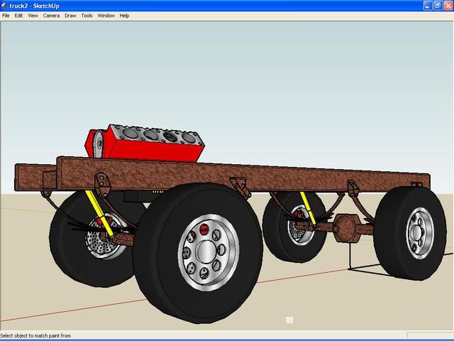
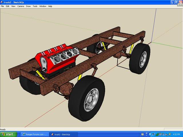
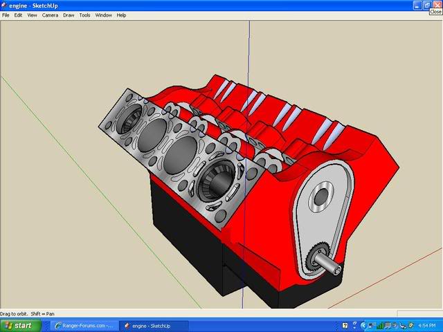
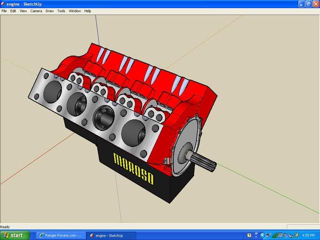
I wish I had Autocad on my home computer but it is too expensive. I use google sketch-up which is a free program but is basic and limited and very frustrating to work with compared to autocad. Here are two things I drew for fun but not to scale, they are far from finished:
Sorry to hack the thread, Rich has a good example. Since some of you guys do this for a living: Is it possible to draw a boat propeller on autocad? When I had a cad class I tried it but both the teacher and I found it impossible.
Sorry to hack the thread, Rich has a good example. Since some of you guys do this for a living: Is it possible to draw a boat propeller on autocad? When I had a cad class I tried it but both the teacher and I found it impossible.
Last edited by leadfoot; Jun 4, 2008 at 03:04 PM.

Thread
Thread Starter
Forum
Replies
Last Post
annguyen1981
OLD - Interior, Exterior, Electrical, & Misc.
28
Dec 25, 2011 06:42 PM


