
Door Switch Lighting Idea

Door Switch Lighting Idea
My next LED mod is going to be a bit different. I have been planning to put a strip of LEDs under my doors so that when the door is opened, the LEDs turn on. This would be quite useful at night when there are puddles on the ground and you cant see. It would look like a 'ray of light' sweeps out with the door. I would use blue as it matches the plethora of LEDs I currently have.
Now the technical details.
My plan is to use the switched side of the door switches that 'know' if the door is opened or not. These are the same switches that turn on your dome light when you open the door, or turn on the 'door ajar' light. My plan was to steal power from this switched side.
I do believe I would have to diode isolate the power coming to the LEDs so that they will not turn on when I turn on my dome light. I want them to only come on when the door is opened. I plan to do this to both passenger, and drivers door (only a 2 door truck)
Does this sound like a workable idea? Has anyone done this before?
Also, I think the switch is in the latch, correct? Can anyone shed some 'light' haha.
Why? The electrical system already knows when the door is open. It is just a matter of using the information available. That would be like adding a big carburetor to an engine you've beefed up just because you cant figure out fuel injection.

does that switch have enough power for lights? i might be just some deal where it just sends a signal somewhere and then the lights get power from somewhere else. you could always run a wire from the dome light. little extra work but it's a guarantee.

Well yes but then whenever he turned on his dome light those would light up. He only wants it to light up when the door is open. You could easily wire up a relay with the door switch as the trigger. Hey Jp7 I'll dig out my wiring diagram later and look up the door ajar sensor and see how that circuit works. Hit me up on AIM later
Well yes but then whenever he turned on his dome light those would light up. He only wants it to light up when the door is open. You could easily wire up a relay with the door switch as the trigger. Hey Jp7 I'll dig out my wiring diagram later and look up the door ajar sensor and see how that circuit works. Hit me up on AIM later
Member

Joined: Oct 2008
Posts: 723
Likes: 0
From: Bryan, OH
sorry to thread jack but where are the sensors for the door a jar. Ive gone out and slamed all 4 of my doors and the thing is still on, gets anoying at night.
This is a good idea just dont know how it would work. If you get it to work this might be my next mod.
This is a good idea just dont know how it would work. If you get it to work this might be my next mod.
Member
Joined: Apr 2007
Posts: 83
Likes: 0
From: Norcross, GA
I like the puddle light idea a lot, and it sounds workable.
The things I have to find out is:
Does the switch give 12V or does it give ground?
What are the right colors to give?
If anyone knows this would be nice, my truck is a 2004 2 door extended cab.
I can do some testing but any wiring guru's chime in.
Does the switch give 12V or does it give ground?
What are the right colors to give?
If anyone knows this would be nice, my truck is a 2004 2 door extended cab.
I can do some testing but any wiring guru's chime in.
Will there be clearance at the bottom of the door for the led's? cuz its a tight fit with the ranger plate at the bottom correct?
and as for wiring you could steal some power from fuse 25 or 27 its the one that if you pull it your dome lights will not come on. or just find the wires in the door on the switch you should be fine pulling power off of it. are you also running an ohc?
and as for wiring you could steal some power from fuse 25 or 27 its the one that if you pull it your dome lights will not come on. or just find the wires in the door on the switch you should be fine pulling power off of it. are you also running an ohc?
Will there be clearance at the bottom of the door for the led's? cuz its a tight fit with the ranger plate at the bottom correct?
and as for wiring you could steal some power from fuse 25 or 27 its the one that if you pull it your dome lights will not come on. or just find the wires in the door on the switch you should be fine pulling power off of it. are you also running an ohc?
OK - thanks to Trent (who gave me the wire colors) i Pre-tested this mod today:
The door latch has the switch in it, and it is switched ground.
I hooked my meter between the Battery Positive, and the yellow/black wire on the latch on the drivers side door.
When the door is open I get 12.2V.
When the door is closed I get between .9 and .7 V.
You would think this should be zero.
I am at a loss for this, as with .9V the LEDs will barely come on just a little bit.
Maybe when the switch is open, it is not really open, just high resistance?
Can someone shed some light on this?
You need to use the wire that triggers the dome light when the door is open to be ran to pin 86 on the relay. This will take the low amperage from that circuit and apply it to the relay to trigger a 12v system on pin 87 which will run to the lights. Pin 30 is constant power and 85 is ground.
Member

Joined: May 2005
Posts: 1,179
Likes: 8
From: San Diego, CA

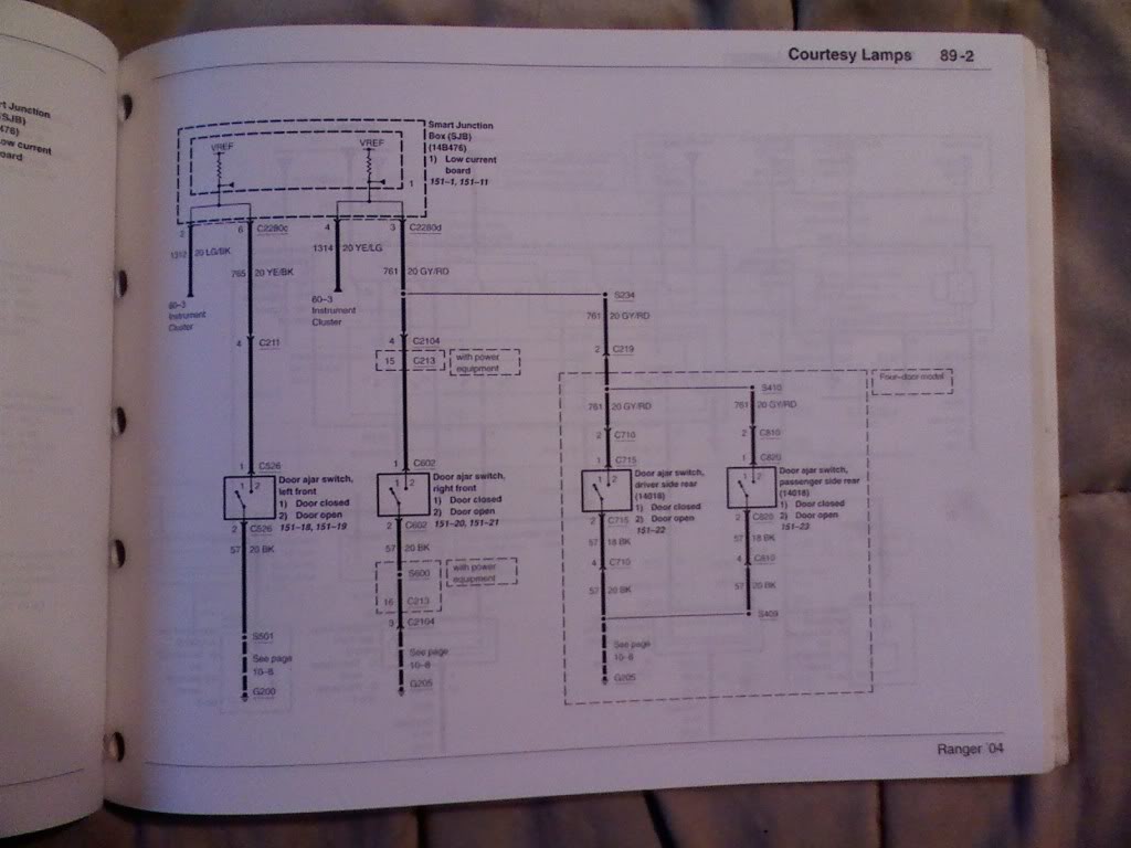
I believe you’ll find that the door switch is tied into the GEM. The circuit simply senses either a high or low state on the YE/BK wire, depending on the door switch position (open/closed). The GEM in turn either opens or closes the interior lamp relay, turning on or off the interior lamps.
From what I've read and been told, since the circuit is such a low current draw, it isn't enough to power aux lights like LEDs or like what I have with the lights under the doors, like what Jp7 is trying to do.
You need the relay in the system to do this to trigger a constant 12v circuit using a low amperage circuitt such as the dome light when the doors are open...
Hope that's making sense, I know what I'm trying to say, just don't know if it's coming across in english lol
You need the relay in the system to do this to trigger a constant 12v circuit using a low amperage circuitt such as the dome light when the doors are open...
Hope that's making sense, I know what I'm trying to say, just don't know if it's coming across in english lol
Member
Joined: May 2005
Posts: 1,179
Likes: 8
From: San Diego, CA
I would suspect the circuit operation is still similar to that of the GEM's in older trucks. That would account for the .7-.9V he's seeing when the switch is open due to resistance or volt drop through the circuit (I hooked my meter between the Battery Positive, and the yellow/black wire).

Level I Supporter
Joined: Aug 2006
Posts: 3,657
Likes: 9
From: Durham, NC
The switch is CLOSED, when door is open, causing the full 12.2V reading between BATTERY + terminal and the wire going to the switch. The switch is OPEN when the door is closed, and the reason it doesn't go all the way to 12.2V ( or get 0V with respect to the BATTERY + terminal), is the wire is probably coming off the source of a NFET, and you are seeing a source follower effect, where the source is setting a Vt below the NFET gate.
The switch is CLOSED, when door is open, causing the full 12.2V reading between BATTERY + terminal and the wire going to the switch. The switch is OPEN when the door is closed, and the reason it doesn't go all the way to 12.2V ( or get 0V with respect to the BATTERY + terminal), is the wire is probably coming off the source of a NFET, and you are seeing a source follower effect, where the source is setting a Vt below the NFET gate.
I do not want to put it on the dome light circuit because I do not want the "puddle LEDs" to come on when I turn my dome light on with the switch on the dash, only when I open the door.
Thanks guys


