
Need help finding a special switch


Need help finding a special switch
Hey Guys, Here is what I have and what I want to do...
What I have:
On my 06 FX4 I have a flex-a-lite controller for my e-fan. The controller has two terminals on it that when grounded make the fan turn manual on / and manual off.
What I want:
What I want is a three position, center off, low profile, intergral blue LED, and in cab mounted switch to control it. I'll place it right above the fog light switch on the radio bezel.
The up & down positions would ground the appropriate circut turning on/off the fan and the blue light would be wired directly to the fan so I knew when it was running. (sometimes run automaticly by the controller)
So far I can seem to only find switches with two position on/off and integral blue lights.. or dopy looking, three position, industrial strength center off switches w/o a light.
If I had to run a seperate blue led that's ok I can do that. But I just do not like the HUGE center off toggle switched I find at autozone, or at the local radio shack.
Help!
Regards,
Rich
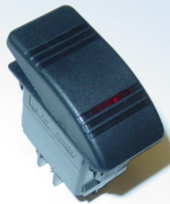
btw, the look of these would be "ok" because they are not too tall:


But I really want the low profile look. (they are $3 at autozone.. round and blend in with the panel nicely)

What I have:
On my 06 FX4 I have a flex-a-lite controller for my e-fan. The controller has two terminals on it that when grounded make the fan turn manual on / and manual off.
What I want:
What I want is a three position, center off, low profile, intergral blue LED, and in cab mounted switch to control it. I'll place it right above the fog light switch on the radio bezel.
The up & down positions would ground the appropriate circut turning on/off the fan and the blue light would be wired directly to the fan so I knew when it was running. (sometimes run automaticly by the controller)
So far I can seem to only find switches with two position on/off and integral blue lights.. or dopy looking, three position, industrial strength center off switches w/o a light.
If I had to run a seperate blue led that's ok I can do that. But I just do not like the HUGE center off toggle switched I find at autozone, or at the local radio shack.
Help!
Regards,
Rich
btw, the look of these would be "ok" because they are not too tall:
But I really want the low profile look. (they are $3 at autozone.. round and blend in with the panel nicely)
Last edited by wydopnthrtl; Aug 6, 2007 at 12:49 PM.
Member

Joined: Nov 2005
Posts: 1
Likes: 4
From: Charlestown, IN
here is what i have in my truck to control my efan (minus the light)....it is a DPDT (they offer DPST also) switch....i know it wont fit were you want it to, but i figure you could mount it in another convient location (i have mine in the side of my Pioneer console)....
switch:
http://shop.genuinedealz.com/Items/gim-es-vjda-b?
my location: (the switch closest to the seat is the DPDT switch)....i have mine setup with a DPDT switch to have Auto/Off/Forced ON....

switch:
http://shop.genuinedealz.com/Items/gim-es-vjda-b?
my location: (the switch closest to the seat is the DPDT switch)....i have mine setup with a DPDT switch to have Auto/Off/Forced ON....
Member
Joined: Feb 2007
Posts: 83
Likes: 0
From: Fishers (Indianapolis), IN
Hum.. not sure I understand the abbreviations properly.
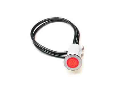
I *think* this switch with a seperate LED light would work. Right?
http://www.delcity.net/delcity/servl...s?item=7000019

I *think* this switch with a seperate LED light would work. Right?
http://www.delcity.net/delcity/servl...s?item=7000019
Last edited by wydopnthrtl; Aug 6, 2007 at 01:41 PM.
Member
Joined: Nov 2005
Posts: 1
Likes: 4
From: Charlestown, IN
yea they will work Rich.....i have a LED hooked into my + lead wire going to the fan....it is located on my gauge column....
here is a picture of my LED location....it is the lower LED....this kinda puts it more in the "line of sight"......the second LED indicates when my blue lights are on (emergency lights for the FD)...


here is a picture of my LED location....it is the lower LED....this kinda puts it more in the "line of sight"......the second LED indicates when my blue lights are on (emergency lights for the FD)...

Originally Posted by lifted97ranger
yea they will work Rich.....i have a LED hooked into my + lead wire going to the fan....it is located on my gauge column....
here is a picture of my LED location....it is the lower LED....this kinda puts it more in the "line of sight"......the second LED indicates when my blue lights are on
here is a picture of my LED location....it is the lower LED....this kinda puts it more in the "line of sight"......the second LED indicates when my blue lights are on
Thanks Maurice, I'm like a 2nd grader when it comes to electrical stuff. 
OK.. just so I don't mistake this and buy the wrong thing. I want a "DPST"?
I take it that means dual position single terminal?
Seems like the only ones I can see that have the center off position... which will allow for neither wire to be grounded.... are "DPDT" switches. I take that to mean they have two sets of terminals. Which I guess would work.. just don't need the extra ones.
Rich
Originally Posted by zabeard
BINGO! That's just about exactly what I was wanting.
Thanks a bunch!
Rich
Member
Joined: Nov 2005
Posts: 1
Likes: 4
From: Charlestown, IN
Originally Posted by zabeard
what size resister did u use behind that LED? mine is way to bright.
Green:
http://www.jegs.com/webapp/wcs/store...0002_623466_-1
Blue:
http://www.jegs.com/webapp/wcs/store...0002_623464_-1
Red:
http://www.jegs.com/webapp/wcs/store...0002_623463_-1
just imagine these with the different colors.....
they also have them in 1/8" & 1/2" LED's.......
the ones i got from Jeg's were the 1/8" versions.......i wanted them to be less noticable as possible on my new gauge pod column....the ones in the pictures i posted above are from Radio Shack...
Originally Posted by wydopnthrtl
Thanks Maurice, I'm like a 2nd grader when it comes to electrical stuff.
OK.. just so I don't mistake this and buy the wrong thing. I want a "DPST"?
I take it that means dual position single terminal?
Seems like the only ones I can see that have the center off position... which will allow for neither wire to be grounded.... are "DPDT" switches. I take that to mean they have two sets of terminals. Which I guess would work.. just don't need the extra ones.
Rich
Double Pole, Single Throw. As in throw one switch and it can switch two items on on separate circuits.
Double Pole Double Throw
and
Single Pole Double Throw
are other type of switches.
Thank a lot guys, now how about a LED. I bought one at murrays last night.. looks like it will work but it's a bit too big IMO.
Will this work with a 12v system?
http://www.allelectronics.com/cgi-bi...IGHT_LED_.html

Will this work with a 12v system?
http://www.allelectronics.com/cgi-bi...IGHT_LED_.html
Member
Joined: Nov 2005
Posts: 1
Likes: 4
From: Charlestown, IN
unless you get a pre-wired LED for a 12v system, you will have to use John Grigg's How-to on resistor selection for your LED.....LED's only draw a small amout of power....if you put a straight 12v to it, it will burn up....
here is John's How-to:
http://www.cardomain.com/ride/296394/13
you will also need to get a LED gromet for the LED to sit in, if not it will be near impossible for it to stay in the hole....
if it were me, i would get the ones from Jeg's that I posted, or go to Radio Shack and get some pre-wired LED's that way you wont have to do the math/figuring to find the proper resistor for the LED to function....
it will work but you need to put a resister on it, like a 10k or larger so its not so bright.
you can get the resistors on that site. or at radio shack. they also have these really nice clip holders.
if you do not solder a resistor on the LED it will get hot and burn out.
you can get the resistors on that site. or at radio shack. they also have these really nice clip holders.
if you do not solder a resistor on the LED it will get hot and burn out.
Member
Joined: Nov 2005
Posts: 1
Likes: 4
From: Charlestown, IN
Originally Posted by zabeard
it will work but you need to put a resister on it, like a 10k or larger so its not so bright.
Originally Posted by lifted97ranger
the resistor doesn't take away brightness, it takes away power since most LED's are a 1-3v LED.....
and when you take away power what does the LED do?

i am just trying to give him the total effect of what it will do, no one notices the voltage dropping.

Um.... I'll try the radio shack thing first.  I have a friend who's an EE. here is what he told me......
Simple explanation: Yes, but you will need a resistor in series of about 560 Ohms.
Technical Details: An LED (or any diode) will conduct infinite current (0 Ohms resistance) with a a fairly fixed voltage drop (volts) when voltage is applied. Recall a couple of formulas:
1) Power = Volts * Amps
2) Volts = Amps * Ohms
Given that an LED has a resistance of 0 will mean (theoretically) a current (Amps) of Infinity. This will mean that the power in equation one will go to infinity and burn something out (either a fuse or the LED -- probably the LED).
I noticed that this LED has a forward drop (voltage drop across it) of 3.17Volts and a current of .020 Amps from some of the comments from users on the webpage. How can I create this happy operating state? Lets examine equation #2:
Volts = Amps * Ohms
I know that Volts is fixed ~14.4 in a car and I know that when I put .020 Amps into the diode it will drop 3.17 volts and I cannot change these numbers. The volts side is now:
(14.4 - 3.17) = Amps * Ohms
I know the LED likes .020 Amps, so now I have:
(14.4 - 3.17) = .020 * Ohms
Ohms = (14.4-3.17)/.020 = 561
The standard resistor sizes for 5% accurate resistors are 510, 560, 620, and 680. I would try a 560. If it is too bright, go to a 620. If it is not bright enough, go to a 510. A smaller resistor will allow more current and thus a brighter light although at some point you will begin to reduce the longevity of the LED. Of course, like anything in engineering all of the equations above shift over temperature.
Here is a nice page on the topic:
http://led.linear1.org/1led.wiz (you would use 14.4, 3.17, and .020 in this simulator)
PS. It is important which end of the LED is connected to + and - voltage, but it does not matter if the resistor is between the battery and the LED or the LED and ground. Have fun
I have a friend who's an EE. here is what he told me......Simple explanation: Yes, but you will need a resistor in series of about 560 Ohms.
Technical Details: An LED (or any diode) will conduct infinite current (0 Ohms resistance) with a a fairly fixed voltage drop (volts) when voltage is applied. Recall a couple of formulas:
1) Power = Volts * Amps
2) Volts = Amps * Ohms
Given that an LED has a resistance of 0 will mean (theoretically) a current (Amps) of Infinity. This will mean that the power in equation one will go to infinity and burn something out (either a fuse or the LED -- probably the LED).
I noticed that this LED has a forward drop (voltage drop across it) of 3.17Volts and a current of .020 Amps from some of the comments from users on the webpage. How can I create this happy operating state? Lets examine equation #2:
Volts = Amps * Ohms
I know that Volts is fixed ~14.4 in a car and I know that when I put .020 Amps into the diode it will drop 3.17 volts and I cannot change these numbers. The volts side is now:
(14.4 - 3.17) = Amps * Ohms
I know the LED likes .020 Amps, so now I have:
(14.4 - 3.17) = .020 * Ohms
Ohms = (14.4-3.17)/.020 = 561
The standard resistor sizes for 5% accurate resistors are 510, 560, 620, and 680. I would try a 560. If it is too bright, go to a 620. If it is not bright enough, go to a 510. A smaller resistor will allow more current and thus a brighter light although at some point you will begin to reduce the longevity of the LED. Of course, like anything in engineering all of the equations above shift over temperature.
Here is a nice page on the topic:
http://led.linear1.org/1led.wiz (you would use 14.4, 3.17, and .020 in this simulator)
PS. It is important which end of the LED is connected to + and - voltage, but it does not matter if the resistor is between the battery and the LED or the LED and ground. Have fun

Thanks guys, I'll give it a try. It seems like a fun and easy little project.
Since it's a light that will be on/off quite often I think I'd like to have it a bit on the dim side. Something that won't draw too much attention and be a constant distraction. Know what I mean?
Just how bright of a difference would I see in a 510 vs a 680?
Also, Just in case the wire were to ground out, I'll put a fuse up near the controller. What size fuse should I use?
Rich


