Mazda B3000 2003 Vacum Hose Routing : translation help
#1
Mazda B3000 2003 Vacum Hose Routing : translation help


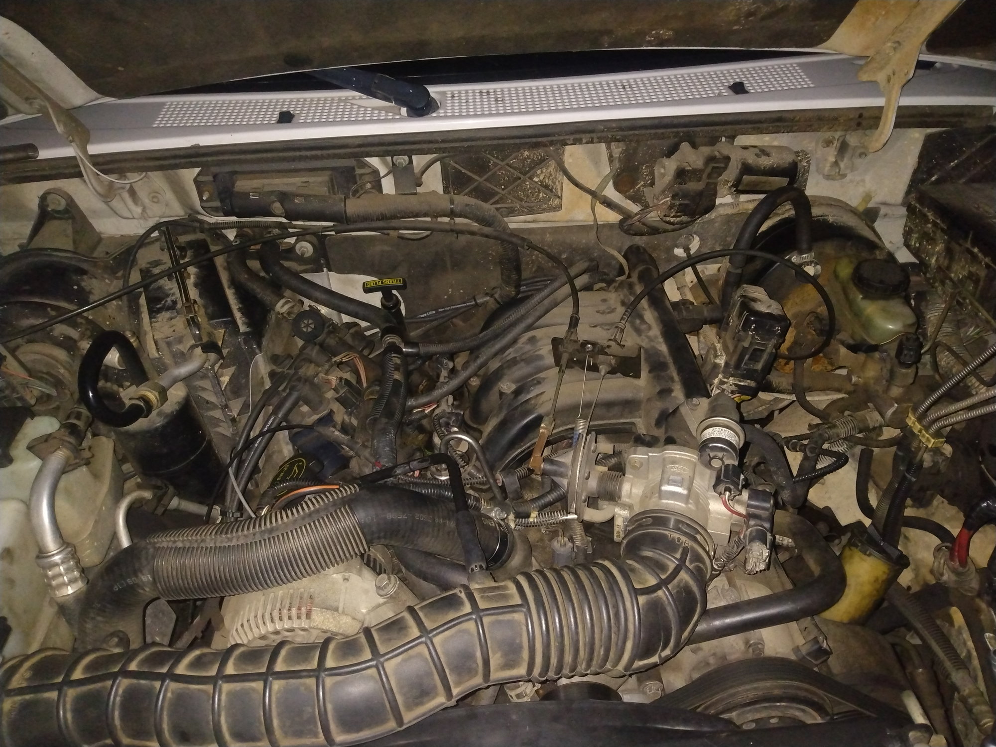
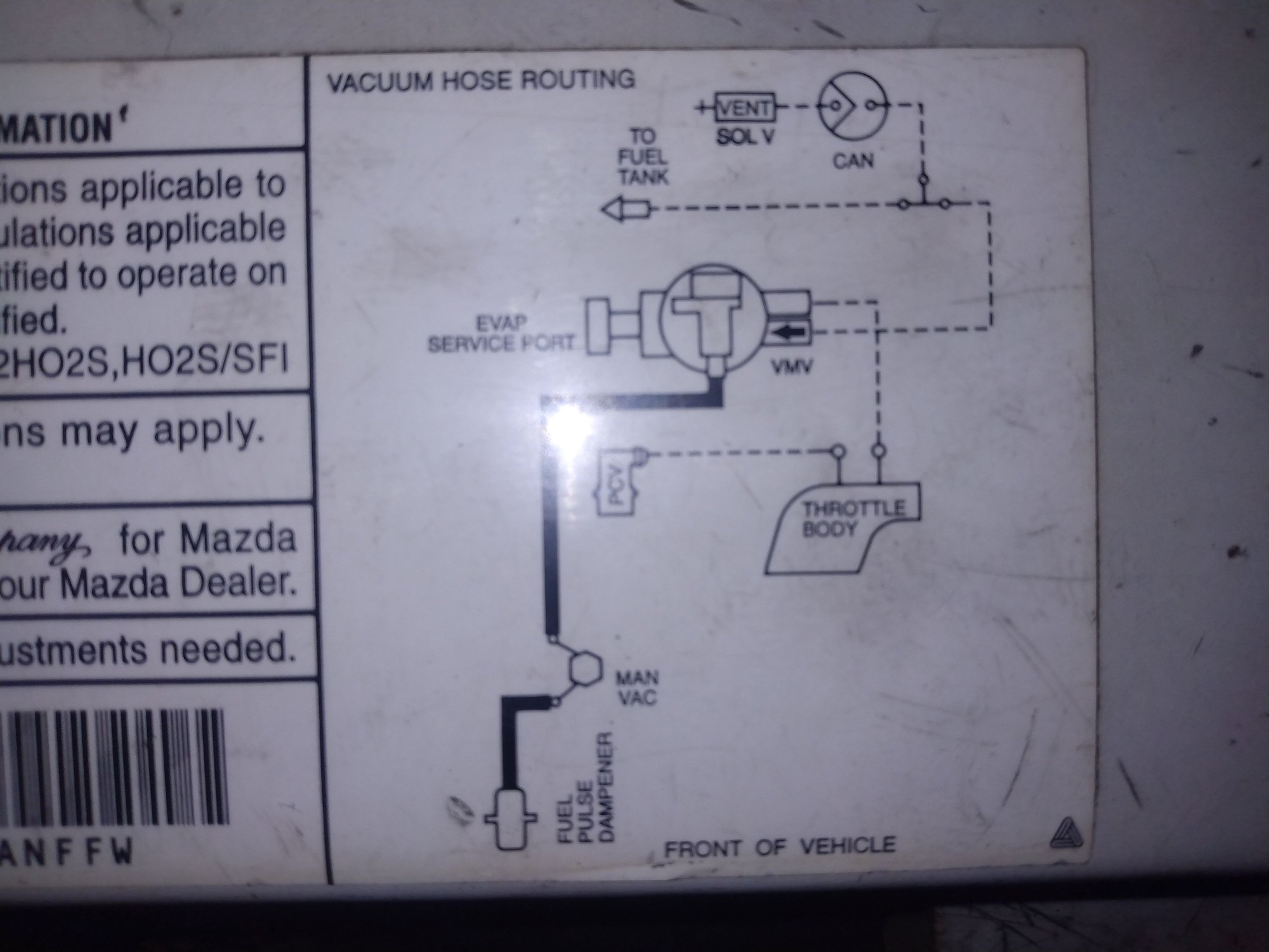
Rear manifold vacuum. Man Vac in Vacuum Routing Diagram

Vacuum Hose Routing for Mazda B3000 2003 V6 and 2000-4 Ford ranger

Intake fuel pulse dampener or FPD. The wire attached to it runs to the front vaccuum on the right side of the throttle body in front of the intake manifold

2 vaccum hoses running from the throttle body to the Evap service port. One goes to the Evap service port along with the red wire running from the fuel pulse dampener (FPD). The other travels to the back of the truck to the evaporative emissions canister and solenoid and fuel tank.

front of vechile. Air intake / upper radiator hose. Intake manifold in the back.
I would appreciate if someone can translate the manufacturer's Vacuum Hose Routing Diagram into a more practical and easy to understand diagram.
The official diagram is in 2d and hard to trance. You have to break it down into sections to understand what's going on. It's hard to trace the vacuum hose by just starting at the 'front of the vechile'. Thanks.

PCV valve between crank case and vaccuum hose
Last edited by Elfexia_Motors; 02-10-2022 at 10:02 AM.
#2
Not sure what you are after, vacuum diagrams never show "routing" of hoses just what they are used for, whats connected to what, not location of hoses
And the diagram shown is just for Emissions system, doesn't include other systems
Power brake booster
Vacuum reservoir and cab vent system
Air pre-heater on air cleaner housing
Are not shown
SOL is solenoid
CAN is charcoal canister(EVAP system), its behind the gas tank in your year
VMV vacuum modulation valve
MAN VAC is intake manifold vacuum
PCV <<<< this one is odd, should be hooked to MAN VAC
Throttle body, is Ported Vacuum, air passage between throttle plate and Air cleaner, PCV Breather hose is on this, not the PCV Valve
And EVAP also uses it
Pulse Damper is on the fuel rail and shown in one of your pictures, pic just below Diagram pic
I don't think I have ever seen a routing diagram for vacuum lines, Ford Service manuals may have them
Last edited by RonD; 02-10-2022 at 11:11 AM.
#3
Ron Reply
Thanks for clarifying. I was trying to route the path of the emissions vacuum hoses by trying to trace the black lines and dotted lines in the diagram starting with the FPD. However, while referring to the diagram, I could not seem to figure out how the different components in the diagram are connected to each other.
By the PVC valve being "odd", are you referring to it's placement in relation to the other components in the diagram or my picture / description of it?
the PVC valve is between the crankcase and the vacuum hose ( is this what they refer to as MAN VAC?)from what I see as shown in the picture above. You have to take off the hose to reveal the PCV valve.
Thanks.
#4
Ron Reply
Thanks for clarifying. I was trying to trace the vacuum route and make sense of things. Following the diagram with my finger, I started at the FPD on top of the fuel rail and kept getting stuck trying to find the intake manifold Vacuum at the back of the manifold toward the firewall.
I then tried tracing the manifold vac to the Evap port but kept getting sidetracked.
The FPD uses a red wire to run to the side of the throttle body (front vaccuum?) and then connects with another red wire at this point that runs to the EVAP service port with a green dial. This confused me because I thought the black line running from the FPD was suppose to represent a hose not a red wire.
By the pcv valve being "odd" are you referring to it's placement in the diagram relative
to the other components (i.e., dotted lines connect it to the throttle body rather than man vac)?
I then concluded that perhaps the diagram was broken into sections and not actually routing the the emissions vac hoses.
My logic was, "how can the man vac be closer to the front of the vechile' than the throttle body if I see here that it's further away near the firewall". Reading the diagram from front of vechile' and associating that with the grill of the vehicle where the radiator is.
Would be nice if you could actually trace the vac hoses from the diagram to find components. It all started with me trying to find the PCV valve to replace it.
Last edited by Elfexia_Motors; 02-10-2022 at 12:59 PM. Reason: change
Thread
Thread Starter
Forum
Replies
Last Post
Updog_
General Technical & Electrical
1
05-06-2019 01:51 PM


