


Relays

 Relays



I'm an eletrical noob too. This is a little different but might help.
https://www.ranger-forums.com/forum2...stock-fog.html
https://www.ranger-forums.com/forum2...stock-fog.html
Member

Joined: Mar 2008
Posts: 1,441
Likes: 0
From: locust grove georgia
Here's the diagram I created for another user:
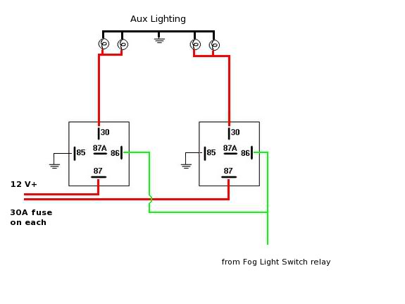
In this diagram, I'd use 10 ga. wiring for the red wires, and 16 ga. wires for the green. Put a 30A fuse on each of the red supply wires from the battery, and a 2A fuse on the green wire from the switch.
In this diagram, I'd use 10 ga. wiring for the red wires, and 16 ga. wires for the green. Put a 30A fuse on each of the red supply wires from the battery, and a 2A fuse on the green wire from the switch.
Yes. the switch isn't shown in that diagram, because the guy I drew it up for was going to be using his stock foglight switch to control them, and he already had a diagram that detailed how to wire a relay to the (negative trigger) factory switch to create a positive trigger.
You could also, just as easily (and more safely, running only a ground wire through the firewall!) hook pin 85 of each relay to a 2A fused power connection, then run the green wire back to your switch, and the other side of the switch to ground.
You could also, just as easily (and more safely, running only a ground wire through the firewall!) hook pin 85 of each relay to a 2A fused power connection, then run the green wire back to your switch, and the other side of the switch to ground.
Member
Joined: May 2009
Posts: 380
Likes: 0
From: Kansas City, MO
The relays shown in the diagram are SPDT relays...meaning they pull one set of contacts to two positions. There are relays out there called DPDT that pulls a set of contacts with one coil in the relay. I did a quick and dirty diagram of what it would generically look like...basically same thing as what turbo had, but with one relay instead of two.



Yes. the switch isn't shown in that diagram, because the guy I drew it up for was going to be using his stock foglight switch to control them, and he already had a diagram that detailed how to wire a relay to the (negative trigger) factory switch to create a positive trigger.
You could also, just as easily (and more safely, running only a ground wire through the firewall!) hook pin 85 of each relay to a 2A fused power connection, then run the green wire back to your switch, and the other side of the switch to ground.
You could also, just as easily (and more safely, running only a ground wire through the firewall!) hook pin 85 of each relay to a 2A fused power connection, then run the green wire back to your switch, and the other side of the switch to ground.

I drew that diagram for someone that was going to be running 4x 150W (600W, total) lights. You can safely run 350-400W on one (30A) relay, but definitely no more than that.

Thread Starter
|
Member
Joined: Dec 2008
Posts: 3,390
Likes: 3
From: Plattsburgh, New York
My FF's are 100watts and I plan on up-gradeing the two news ones to 100watts also, I'd rather be safe with two then just one. But thanks for the diagram, I'm going to get back to wireing them. I'll get pics when I'm done
Ah gotcha, didn't know that.

Thread
Thread Starter
Forum
Replies
Last Post
FMD
General Technical & Electrical
4
Dec 8, 2005 04:41 PM


