


Gauge Cluster - Separating Tach from the rest.



Yes, you need to do what Shane's thread says. Or, I guess you can go down the road and have someone tell you how fast you are going and just put your needle on. Thats the not safe way though. Trust me, its hard to hold a phone, steer, and try to put a needle on

I’ve located a Ford Wiring diagrams Book and won the bid of $10 but received a 2005 Book instead.
Got that problem fixed the new book should be here by Friday.
I need to check out the Indicator Lights and see what I can do.
I got the 2000 Gauge Cluster w/o the Tach for 5 sp, so I am in “GO” mode.
Just need to plug in the cluster and see what works, then if the wiring book gets here I can compare things.
the Power vs ground switching could be a problem I need to talk to someone about that.
ltr and thanks...
Got that problem fixed the new book should be here by Friday.
I need to check out the Indicator Lights and see what I can do.
I got the 2000 Gauge Cluster w/o the Tach for 5 sp, so I am in “GO” mode.
Just need to plug in the cluster and see what works, then if the wiring book gets here I can compare things.
the Power vs ground switching could be a problem I need to talk to someone about that.
ltr and thanks...

Hey Sandy.
I'm doing some diagram comparisons as to what the plugs on the back of the cluster do. I'm comparing 2000 and 2001 and 2003. I have a 2001 book in front of me and am using an online ford diagram book for the other two. Used both ALOT for my engine swap comparing sensor pigtails and their functions when wiring up my hybrid 01/06 engine/trans harness. Here's what I found...
So...just as I suspected, It appears as though it's a straight up swap. I can't find diagrams of the ribbin on the back of the cluster, but that would further confirm what I believe to be correct.
Thow it in!
I'm doing some diagram comparisons as to what the plugs on the back of the cluster do. I'm comparing 2000 and 2001 and 2003. I have a 2001 book in front of me and am using an online ford diagram book for the other two. Used both ALOT for my engine swap comparing sensor pigtails and their functions when wiring up my hybrid 01/06 engine/trans harness. Here's what I found...
So...just as I suspected, It appears as though it's a straight up swap. I can't find diagrams of the ribbin on the back of the cluster, but that would further confirm what I believe to be correct.
Thow it in!
Hey Sandy.
I'm doing some diagram comparisons as to what the plugs on the back of the cluster do. I'm comparing 2000 and 2001 and 2003. I have a 2001 book in front of me and am using an online ford diagram book for the other two. Used both ALOT for my engine swap comparing sensor pigtails and their functions when wiring up my hybrid 01/06 engine/trans harness. Here's what I found...
So...just as I suspected, It appears as though it's a straight up swap. I can't find diagrams of the ribbin on the back of the cluster, but that would further confirm what I believe to be correct.
Thow it in!
I'm doing some diagram comparisons as to what the plugs on the back of the cluster do. I'm comparing 2000 and 2001 and 2003. I have a 2001 book in front of me and am using an online ford diagram book for the other two. Used both ALOT for my engine swap comparing sensor pigtails and their functions when wiring up my hybrid 01/06 engine/trans harness. Here's what I found...
So...just as I suspected, It appears as though it's a straight up swap. I can't find diagrams of the ribbin on the back of the cluster, but that would further confirm what I believe to be correct.
Thow it in!
Hey man, wow, that is great work, thanks.
I do not have my 03 Wiring Book yet but hopefully soon, what about the 03 Theft indicator, is it the same or different location/type of switch ?
From what you are saying they should be the same, so what I will do first is review the Wiring Diagrams, then take everything apart and pull in the ’00 Gauge Cluster and make some notes as to what is on and what isn’t (indicators that is).
Looking at the gauge face and the ’00 Instrument Panel in the Operator’s Manual, all of the indicators are there except for the 4x4 High/low and Fuel Chk. Also the pictures for the indicators may not be exactly the same too.
Since you said they connector are the same they should work no matter where the indicator are located.
So I will need to locate the 4x4 wire to add some LEDs near the actual switch and maybe a Gas Chk.
Here is some more stuff I have to consider, power switching vs ground switching:
4x4 lights are not shown in the O/M for the tachless 2000 cluster. This is just a bulb thing so it shouldn't affect anything else. Using added LEDS for 4x4 and 4Low should be possible using keyed power and the 2 switched grounds in the cluster harness.
The 2000 connector pinout for tach and tachless clusters looks the same as 2003 except:
1) The inertial switch reset wire in 2000 has been replaced by a fuel cap off wire in 2003. This shouldn't matter for the 2000 tachless cluster since it has neither anyway.
2) The Theft LED has switched power in 2000 but switched ground in 2003. So, chances are that it would no longer work.
The 2000 connector pinout for tach and tachless clusters looks the same as 2003 except:
1) The inertial switch reset wire in 2000 has been replaced by a fuel cap off wire in 2003. This shouldn't matter for the 2000 tachless cluster since it has neither anyway.
2) The Theft LED has switched power in 2000 but switched ground in 2003. So, chances are that it would no longer work.
Thanks a lot guys, I will probably be back asking MORE questions.
I need to get the Wiring Diagrams Manual and check thing out too.
Maybe aI need a 2000 Manual too.
ltr,
Last edited by Scrambler82; Dec 1, 2009 at 05:44 PM.
In the '00 connector view diagram, they call wire # 6 the "RAP module input". On the '01-03 they call #6 the "Anti-theft indicator input". Both are circuit #343 and both are Dark Blue/Light Green wires in color.
In theory, it should all work. plug it in and go. Maybe swap your theft LED from your stock cluster to whatever the indicator of "RAP" is on the '00 cluster. And wherever that wire in particular leads to on the cluster, if there's nothing there. Maybe hitup a craft store and cut out a chunk of overlay. Behind the overlay, lay down a chunk that you cut out of our '03's overlay that'll make the theft light display. Same thing can be done on the 4x4 stuff if you wish. Just throwing ideas out...no clue how good looking or hard it'll be.
I'm not all too familiar with the non-tach clusters. I don't recall seeing them in any 4x4's, though I could be wrong. You can probably tell on your existing cluster in the '03, you can see the indicator for the 4x4, cruise, etc...all the clusters are like that. Even ones found on 01 XL's w/o cruise w/o 4x4 w/o PATS(theft light). Are any of those visible on the non-tach cluster?
And for what it's worth, I wouldn't care if the gauges don't show 4x4 hi or 4x4 low. But....here's a diagram of the 16 wire big plug and a breakdown of the wires...

In theory, it should all work. plug it in and go. Maybe swap your theft LED from your stock cluster to whatever the indicator of "RAP" is on the '00 cluster. And wherever that wire in particular leads to on the cluster, if there's nothing there. Maybe hitup a craft store and cut out a chunk of overlay. Behind the overlay, lay down a chunk that you cut out of our '03's overlay that'll make the theft light display. Same thing can be done on the 4x4 stuff if you wish. Just throwing ideas out...no clue how good looking or hard it'll be.
I'm not all too familiar with the non-tach clusters. I don't recall seeing them in any 4x4's, though I could be wrong. You can probably tell on your existing cluster in the '03, you can see the indicator for the 4x4, cruise, etc...all the clusters are like that. Even ones found on 01 XL's w/o cruise w/o 4x4 w/o PATS(theft light). Are any of those visible on the non-tach cluster?
And for what it's worth, I wouldn't care if the gauges don't show 4x4 hi or 4x4 low. But....here's a diagram of the 16 wire big plug and a breakdown of the wires...
YUP !
That’s what I am going to do, plug it in, check out the indicators, make a wire or two change and let it go.
Thanks again for all of the help.
As soon as I get the Wiring Book I will find the 4x4 indicator wiring and see what kind of power is on them when the switch is on and attempt to wire up the LED Indicators near the OEM Sw for both high and low.
Also, I need to make sure about the Theft Indicator switching power or ground as rwenzing has stated and that should do it.
If no smoke then it will be a go.
ltr
That’s what I am going to do, plug it in, check out the indicators, make a wire or two change and let it go.
Thanks again for all of the help.
As soon as I get the Wiring Book I will find the 4x4 indicator wiring and see what kind of power is on them when the switch is on and attempt to wire up the LED Indicators near the OEM Sw for both high and low.
Also, I need to make sure about the Theft Indicator switching power or ground as rwenzing has stated and that should do it.
If no smoke then it will be a go.
ltr
Found a 2000 Ford Wiring Diagram Manual on E-Bay for $10.
Waiting to see what condition item I receive was suppose to be in good condition no markings ion pages.
Once I get them I will compare all of the connector pin-outs and get back at you guys.
Oh ya here is the site for all of the items available from the guy I bought the 2000 Manual form:
All kinds of Ford Wiring Diagrams Manuals for Ranger under $15; some early ones too, < 1995.
eBay Seller: papijoe2002: Parts Accessories items on eBay Motors
Waiting to see what condition item I receive was suppose to be in good condition no markings ion pages.
Once I get them I will compare all of the connector pin-outs and get back at you guys.
Oh ya here is the site for all of the items available from the guy I bought the 2000 Manual form:
All kinds of Ford Wiring Diagrams Manuals for Ranger under $15; some early ones too, < 1995.
eBay Seller: papijoe2002: Parts Accessories items on eBay Motors
- 95~00 has a constant ground and a switched hot from the RAP Module;
- 01~03 has a constant hot and the PCM switches ground.
10-4. I understand now. I think I should have read the first page of the thread. lol. Little bit of soldering and wire should cure this groundground issue, yes? To make the theft light functioning in his '03 truck with a '00 cluster?
In my head I got it....but I can't type it out. Isolating the contacts the bulb holder rides on. Soldering a wire onto each. One going to the factory pigtail in spot #6. One going to a ground. May not have to isolate both sides, but I would for the hell of it just to be sure nothing else in the cluster is tied into that circuit.
Yes, the color code and pin number are the same but, in the factory circuits:
- 95~00 has a constant ground and a switched hot from the RAP Module;
- 01~03 has a constant hot and the PCM switches ground.
If I take an ignition hot and apply it to the uncontrolled ground side of the Theft Light (Pin 6 - Circuit 343 - DB/LG), then the controller side of the theft light should still work through the PCM.
Right or Wrong ?
Looking at the two panels, it appears that the only difference in appearance is the Theft and the 4x4 Indicators.
The theft indicator is mentioned above the 4x4 indicators looks to me only to need to pick up the wires from pins 2, Circuit 784, LB/BK & 3, circuit 783, GY; determine if hot or ground and add LEDs to those wires, again right or wrong?
In the 4x4 Circuits (per C220a pin out) pins 2 and 3; are these hot and controlled by the PCM or are they Grounded waiting got a Hot ?
Sorry for all of the questions but without the books I am lost.
Thanks

Then start rewiring to fit what “I” want it to look like.
NOW… since there are more than a few people on this site that know FAR more than I ever will about automotive electrics, I listen and ask questions; especially when they want to talk to me and I THANK them for that.
My suggestion to you is this, “IF YOU DON’T LIKE ME TALKING TO THESE GUYS AND YOU THINK WHAT I AM ASKING IS STUPID, THEN DON’T READ IT”.
korey89,
THANKS for your comments though, they were useful in determining the capacity of some people to understand that we all don’t know everything and AGAIN "thank GOD" that there are some people that do understand and are willing to help.
AND another question arises, what about the Tach feed lines on the 03 Connector, do they have to be terminated.
Does the computer get feed-bak from RPMs.
I have a 5-sp so shifting isn’t a problem but I just don’t understand how the computer interfaces with the rest of the vehicle.
Does the computer get feed-bak from RPMs.
I have a 5-sp so shifting isn’t a problem but I just don’t understand how the computer interfaces with the rest of the vehicle.
The 2003 has a 220 ohm current limiting resistor in the cluster in series with Theft LED. The 2000 LED resistor is undocumented in the Wiring Manual so it could be in the cluster or could be in the RAP Module. You'll need to check the cluster traces.
The 4x4 lights have common keyed power on pin 5 of C220a (orange/black). Pin 2 (low range) and/or pin 3 (4WD) get grounded to turn the lights on. The ground is supplied by the 4WD Module (electric t-case) or by a position switch (manual t-case).
AND another question arises, what about the Tach feed lines on the 03 Connector, do they have to be terminated.
Does the computer get feed-bak from RPMs.
I have a 5-sp so shifting isn’t a problem but I just don’t understand how the computer interfaces with the rest of the vehicle.
Does the computer get feed-bak from RPMs.
I have a 5-sp so shifting isn’t a problem but I just don’t understand how the computer interfaces with the rest of the vehicle.
Will the tach leads at the connector run an aftermarket tach ?
Actually Kory89, the computer controls are a little more intense in the newer Ranger and I want to add a 4.72L V-8 (289 cu ins) in the future, so I do not want to screw things up so bad now that when I get to the V-8 I will be even more lost than I am now.
AFAIK, the pulse on the factory tan/yellow can be used for the tach signal to any common accessory tach.
The PCM supplies fuel and spark at the correct time so it has to know internally what the exact RPM is. This info comes from the Crank Position Sensor that sends a pulse to the PCM every 10 degrees of crank rotation.
AFAIK, the pulse on the factory tan/yellow can be used for the tach signal to any common accessory tach.
AFAIK, the pulse on the factory tan/yellow can be used for the tach signal to any common accessory tach.
Thanks
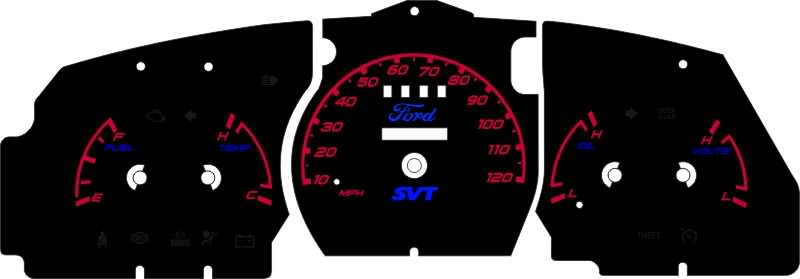
The RED Gauge Faces are made but the even lighting is another thing… working on it.
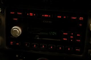
Working on the Radio too.
Here is a pic, a bad one but the best I could get, I doctored it a little just to et it to look this good.
There is a "How-To” in the works.
[
Will update as soon as things change.
Working on the Radio too.
Here is a pic, a bad one but the best I could get, I doctored it a little just to et it to look this good.
There is a "How-To” in the works.
[
Will update as soon as things change.

Thread
Thread Starter
Forum
Replies
Last Post
ranger64
General Technical & Electrical
1
Jul 3, 2014 12:28 AM
Vince near Seattle
Interior Semi-Tech
1
Oct 31, 2009 08:53 PM
01xltranger4x4
General Technical & Electrical
16
Feb 3, 2006 11:53 PM


