P1451/Purge Valve Solenoid Issue
#1
 10-15-2015


Join Date: Oct 2015
Location: Devils Lake, ND
Posts: 4
Likes: 0
Received 0 Likes
on
0 Posts
P1451/Purge Valve Solenoid Issue
First off I will start by saying that I am a noob to the forum so please correct me if I am doing anything wrong...lol.
Well I bought this ranger with the check engine light on and the old owner told me it was an o2 sensor, well that was wrong. I read the codes and p1451 came up. No big deal, I replace the Purge Valve and the Solenoid by the charcoal canister. Well the light still came back. So like I should have done in the first place because it would have saved me a little money, I started checking to see if all my components were getting electricity. Well everything came back good under the hood, but when I checked the actual Solenoid that I replaced, it was getting no power. So I checked the wires, and they were fine, so I traced them all the way to their harness/connector that is right above the fuel filter... Once I unplugged it to see if there was any corrosion, I found out that there were prongs broken off of the actual plug because of corrosion and that was the reason it was throwing the code the whole time.
Needless to say I'm looking into replacing the harness but I can not find the name of the part to save my life, and I'm trying to avoid taking it into the shop for them to tell me what I already know and try to charge me an arm and a leg to fix. If anyone can help it would be appreciated!
Thanks
Brandon
#2
10-15-2015


Your best bet will be a wrecking yard, where you can get both ends of the connector set, if one side is corroded they both are corroded.
And it can be any connector set that has the correct number of wires, so you can get new sets from auto parts store or Ford dealer.
Google: Replacing Ford wiring connections
There is a video that shows how to remove pins from connectors
It depends on how much work you want to do on this, cutting all the wires and re-pinning using the Ford connectors would be stock approach, assuming you have enough slack in the wires to do this, but this type of connector DID fail so not very weather proof for it's location.
Getting a 3rd party weather proof connector and using crimp-splices with dielectric grease and heat shrink might be a better long term solution.
Examples of 3rd party water proof kits: http://www.ebay.com/bhp/wire-connectors-waterproof
These are available at most auto parts stores
Last edited by RonD; 10-15-2015 at 11:23 AM.
#3
10-15-2015
Join Date: Oct 2015
Location: Devils Lake, ND
Posts: 4
Likes: 0
Received 0 Likes
on
0 Posts
Your best bet will be a wrecking yard, where you can get both ends of the connector set, if one side is corroded they both are corroded.
And it can be any connector set that has the correct number of wires, so you can get new sets from auto parts store or Ford dealer.
Google: Replacing Ford wiring connections
There is a video that shows how to remove pins from connectors
It depends on how much work you want to do on this, cutting all the wires and re-pinning using the Ford connectors would be stock approach, assuming you have enough slack in the wires to do this, but this type of connector DID fail so not very weather proof for it's location.
Getting a 3rd party weather proof connector and using crimp-splices with dielectric grease and heat shrink might be a better long term solution.
Examples of 3rd party water proof kits: Wire Connectors Waterproof | eBay
These are available at most auto parts stores
But I do have a question for you and or anyone else willing to help. I've searched and searched and searched but I can not find the wiring diagram for the harness I am replacing. Under the truck below the drivers seat and right beside the fuel filter on the frame is where it's located. I am not sure if the dealer is going to send the diagram let alone the pins for the connector and was wondering if anyone knew where to find this?
I'll post some pics of the old harness to see if that will help.
Imgur: The most awesome images on the Internet
Imgur: The most awesome images on the Internet
Imgur: The most awesome images on the Internet
Imgur: The most awesome images on the Internet
Last edited by bmann; 10-15-2015 at 04:59 PM.
#4
10-15-2015


#5
10-15-2015
Thats the C309 connector I believe, it is a common issue now that you described its location.
Google: 2000 Ranger C309 wiring
EDIT:
^^^ yes in 2001 it was called C340, not sure if it exactly the same but it did have the same water intrusion issues
Google: 2000 Ranger C309 wiring
EDIT:
^^^ yes in 2001 it was called C340, not sure if it exactly the same but it did have the same water intrusion issues
Last edited by RonD; 10-16-2015 at 10:44 AM.
#6
10-15-2015
There's actually a TSB related to this connection along with repair recommendations.
TSB
01-5-2
Publication Date: MARCH 2, 2001
FORD:2000-2001 RANGERISSUE:
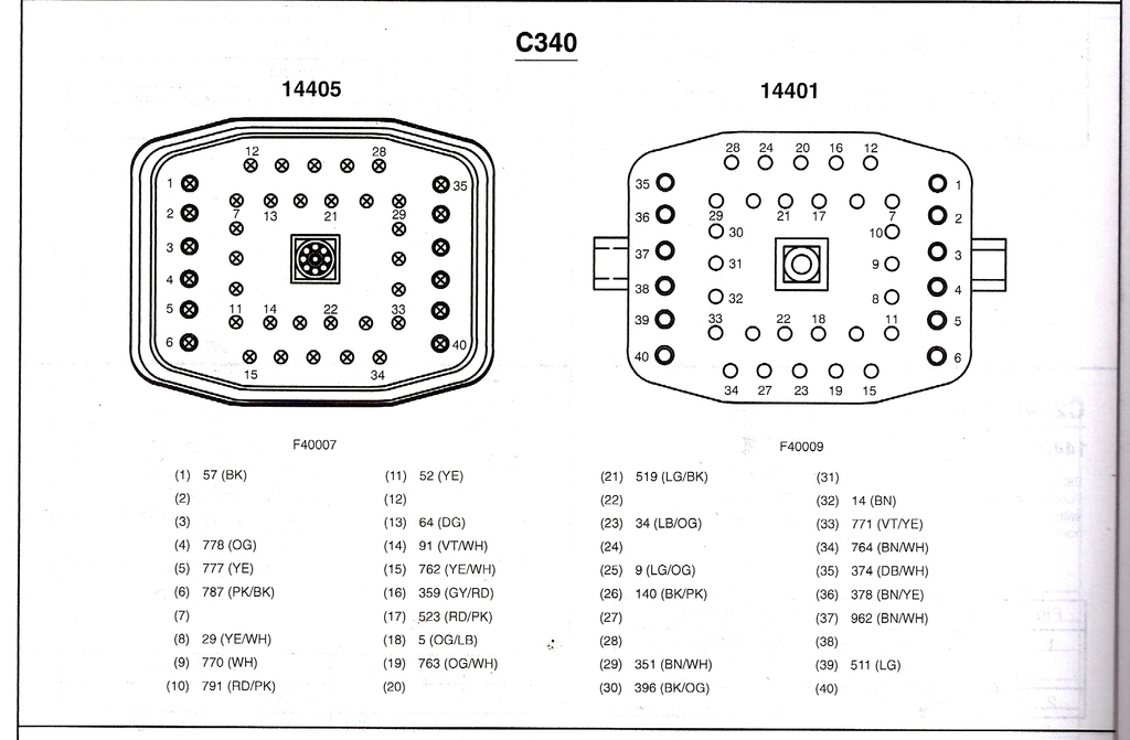
Some vehicles may exhibit a rough idle, Anti-lock Brake System (ABS) warning lamp illumination, inoperative or erratic speedometer, Diagnostic Trouble Codes (DTCs) P0500, P0501, P0503, P1721, P0176, P1000, ABS DTC 9, RABS DTC 16, or a delayed or harsh shifting automatic transmission. This may be caused by water intrusion at connector C309 (2000 model year) or C340 (2001 model year) under the driver's seat.
ACTION:
Inspect affected connectors; clean or replace connector pins as necessary. Install new sleeve and boot assembly over -14401- connector (interior). Refer to the following Service Procedure for details.
SERVICE PROCEDURE
Verify water intrusion in connector C309 for 2000 model year or C340 for 2001 model year applications by removing bottom half (male) connector located on -14405- wire harness assembly under driver's seat, outside, beneath vehicle's cab. If water is present or pins are damaged, remove connector sleeve and perform the following:
INSIDE CAB
Remove driver's seat
Remove driver's door scuff plate
Peel carpet or vinyl lining back to gain access to top portion of connector C309F (for 2000 model year) or C340F (for 2001 model year)
F = Female Side Of Connector
Remove connector from floor pan by depressing locking tabs on side of connector
Remove cap from back of connector to gain access to the pins
Remove red locking wedge from face of connector
Remove each pin individually and clean accordingly NOTE:IF PINS ARE DAMAGED BEYOND THE ABILITY TO CLEAN, OBTAIN NEW PINS FOR REPAIR. ALL PINS WILL REQUIRE SOLDERING TO WIRE FOR MORE ROBUST CONNECTION. REFERENCE APPROPRIATE PINS:F67Z-14487-AA replacing silver finish pins (1.6mm) and/or E6DZ-14487-AA replacing gold/brass finish pins (1.6mm) and/or F6DZ-14487-BA replacing gold/brass finish pins (2.8mm).
When all pins are cleaned or replaced, install new Cap (1L5Z-14A541-AA) over existing connector 14A464
Insert all pins through new Rubber Boot (1L5Z-14A099-AA)
Install pins into existing connector (refer to the appropriate Electrical and Vacuum Troubleshooting Manual (EVTM) for correct pin positions)
Install existing red locking wedge and seat rubber boot to new cap
Insert connector into sheet metal (floor pan area)
OUTSIDE CAB UNDERNEATH VEHICLE/DRIVER'S SIDE
Remove cap from back of connector C309M (2000 model year) or C340M (2001 model year)
M = Male Side Of Connector
Remove white locking wedge from face of connector
Remove each pin individually, clean accordingly, and re-insert into correct cavity of lower connector 14A624 (refer to EVTM for correct pin position) NOTE:IF PINS ARE DAMAGED BEYOND THE ABILITY TO CLEAN, OBTAIN NEW PINS FOR REPAIR. ALL PINS WILL REQUIRE SOLDERING TO WIRE FOR MORE ROBUST CONNECTION. REFERENCE APPROPRIATE PINS:E7EB-14461-BA replacing silver finish pins (1.6mm) and/or F6TZ-14461-AA replacing gold/brass finish pins (1.6mm) and/or F6DZ-14461-CA replacing silver finish pins (2.8mm) and/or E5DZ-14461-A replacing silver finish (1.6mm Circuits 52 and 64)
Install existing white locking wedge and reseat existing cap to back of connector C309M (2000 model year) or C340M (2001 model year)
Apply dielectric grease sparingly to all pins
Slide sleeve over upper connector and lock-in place
Slide lower connector over sleeve and secure with bolt in connector - torque bolt to 4.8 �0.8 N-m (42.5 �7 lb-in)
After connector has been reinstalled, verify concern has been eliminated. Reinstall carpet or vinyl lining, door scuff plate, and driver's seat.
PART NUMBERPART NAME1L5Z-14A099-AARubber Connector Boot1L5Z-14A541-AAPlastic Connector CapF67Z-14487-AAFemale Side - Silver Finish Pins (1.6mm)E6DZ-14487-AAFemale Side - Gold/Brass Finish Pins (1.6mm)F6DZ-14487-BAFemale Side - Gold/Brass Finish Pins (2.8mm)E7EB-14461-BAMale Side - Silver Finish Pins (1.6mm)F6TZ-14461-AAMale Side - Gold/Brass Finish Pins (1.6mm)F6DZ-14461-CAMale Side - Silver Finish Pins (2.8mm)E5DZ-14461-AMale Side - Silver Finish (1.6mm Circuits 52 And 64)OTHER APPLICABLE ARTICLES:
NONE
WARRANTY STATUS:
Eligible Under The Provisions Of Bumper To Bumper Warranty Coverage
TSB
01-5-2
Publication Date: MARCH 2, 2001
FORD:2000-2001 RANGERISSUE:
Some vehicles may exhibit a rough idle, Anti-lock Brake System (ABS) warning lamp illumination, inoperative or erratic speedometer, Diagnostic Trouble Codes (DTCs) P0500, P0501, P0503, P1721, P0176, P1000, ABS DTC 9, RABS DTC 16, or a delayed or harsh shifting automatic transmission. This may be caused by water intrusion at connector C309 (2000 model year) or C340 (2001 model year) under the driver's seat.
ACTION:
Inspect affected connectors; clean or replace connector pins as necessary. Install new sleeve and boot assembly over -14401- connector (interior). Refer to the following Service Procedure for details.
SERVICE PROCEDURE
Verify water intrusion in connector C309 for 2000 model year or C340 for 2001 model year applications by removing bottom half (male) connector located on -14405- wire harness assembly under driver's seat, outside, beneath vehicle's cab. If water is present or pins are damaged, remove connector sleeve and perform the following:
INSIDE CAB
Remove driver's seat
Remove driver's door scuff plate
Peel carpet or vinyl lining back to gain access to top portion of connector C309F (for 2000 model year) or C340F (for 2001 model year)
F = Female Side Of Connector
Remove connector from floor pan by depressing locking tabs on side of connector
Remove cap from back of connector to gain access to the pins
Remove red locking wedge from face of connector
Remove each pin individually and clean accordingly NOTE:IF PINS ARE DAMAGED BEYOND THE ABILITY TO CLEAN, OBTAIN NEW PINS FOR REPAIR. ALL PINS WILL REQUIRE SOLDERING TO WIRE FOR MORE ROBUST CONNECTION. REFERENCE APPROPRIATE PINS:F67Z-14487-AA replacing silver finish pins (1.6mm) and/or E6DZ-14487-AA replacing gold/brass finish pins (1.6mm) and/or F6DZ-14487-BA replacing gold/brass finish pins (2.8mm).
When all pins are cleaned or replaced, install new Cap (1L5Z-14A541-AA) over existing connector 14A464
Insert all pins through new Rubber Boot (1L5Z-14A099-AA)
Install pins into existing connector (refer to the appropriate Electrical and Vacuum Troubleshooting Manual (EVTM) for correct pin positions)
Install existing red locking wedge and seat rubber boot to new cap
Insert connector into sheet metal (floor pan area)
OUTSIDE CAB UNDERNEATH VEHICLE/DRIVER'S SIDE
Remove cap from back of connector C309M (2000 model year) or C340M (2001 model year)
M = Male Side Of Connector
Remove white locking wedge from face of connector
Remove each pin individually, clean accordingly, and re-insert into correct cavity of lower connector 14A624 (refer to EVTM for correct pin position) NOTE:IF PINS ARE DAMAGED BEYOND THE ABILITY TO CLEAN, OBTAIN NEW PINS FOR REPAIR. ALL PINS WILL REQUIRE SOLDERING TO WIRE FOR MORE ROBUST CONNECTION. REFERENCE APPROPRIATE PINS:E7EB-14461-BA replacing silver finish pins (1.6mm) and/or F6TZ-14461-AA replacing gold/brass finish pins (1.6mm) and/or F6DZ-14461-CA replacing silver finish pins (2.8mm) and/or E5DZ-14461-A replacing silver finish (1.6mm Circuits 52 and 64)
Install existing white locking wedge and reseat existing cap to back of connector C309M (2000 model year) or C340M (2001 model year)
Apply dielectric grease sparingly to all pins
Slide sleeve over upper connector and lock-in place
Slide lower connector over sleeve and secure with bolt in connector - torque bolt to 4.8 �0.8 N-m (42.5 �7 lb-in)
After connector has been reinstalled, verify concern has been eliminated. Reinstall carpet or vinyl lining, door scuff plate, and driver's seat.
PART NUMBERPART NAME1L5Z-14A099-AARubber Connector Boot1L5Z-14A541-AAPlastic Connector CapF67Z-14487-AAFemale Side - Silver Finish Pins (1.6mm)E6DZ-14487-AAFemale Side - Gold/Brass Finish Pins (1.6mm)F6DZ-14487-BAFemale Side - Gold/Brass Finish Pins (2.8mm)E7EB-14461-BAMale Side - Silver Finish Pins (1.6mm)F6TZ-14461-AAMale Side - Gold/Brass Finish Pins (1.6mm)F6DZ-14461-CAMale Side - Silver Finish Pins (2.8mm)E5DZ-14461-AMale Side - Silver Finish (1.6mm Circuits 52 And 64)OTHER APPLICABLE ARTICLES:
NONE
WARRANTY STATUS:
Eligible Under The Provisions Of Bumper To Bumper Warranty Coverage
#7
10-16-2015
Join Date: Oct 2015
Location: Devils Lake, ND
Posts: 4
Likes: 0
Received 0 Likes
on
0 Posts
Just a random question, do you think if I went to a salvage yard and couldn't find my specific model/motor that I could pull a plug off of a salvaged ranger and it be fairly universal?
Might be a stupid question, I honestly know nothing about fords, I bought it because I like to wheel and deal lol.
Might be a stupid question, I honestly know nothing about fords, I bought it because I like to wheel and deal lol.
#8
10-17-2015
#9
10-17-2015
Join Date: Oct 2015
Location: Devils Lake, ND
Posts: 4
Likes: 0
Received 0 Likes
on
0 Posts

Thread
Thread Starter
Forum
Replies
Last Post
briz
SOHC - 2.3L & 2.5L Lima Engines
18
01-16-2017 07:20 PM


