When you click on links to various merchants on this site and make a purchase, this can result in this site earning a commission. Affiliate programs and affiliations include, but are not limited to, the eBay Partner Network.
Hello I'm back working on my 87 Bronco2 with 97 Ranger 4.ol implant. As I stated in many threads the wiring change over is a nightmare. My question tonight is some wire circuits in the under the hood PDB ,are hot at all times and some are run or start? With my build do I need another fuse panel for the run and start. The PCM relay seems to have both. Does the wiring in the PDB separate them or is it hot at all times? When the 97 running gear was in the Ranger it had the Cab fuse panel. I only have the 87 Bronco inside panel. Do I add a new fuse box for the start run circuits?. I don't have the 97 Ranger dash harness. Thx
The EEC/PCM relay's coil RUN 12v and its 12v not cut when in START, it powers the PCM, spark system, fuel injectors, fuel pump "relay", and any solenoids used for engine or transmission operation
Only wire in engine bay that just has 12v in START is the red/blue wire at starter relay(solenoid), it comes from the clutch switch in the cab or the Neutral switch on trans if automatic
Except for the PCM Relay there are no other Key On wires or fuses in engine bay that comes from the ignition switch
Ignition switch powers on most Cab fuse box fuses, but there are full time power fuses in cab fuse box as well
Ron thank you a great help to me. One thing would please make the line a little easier for this old guy to grasp. The EEC/PCM relay's coil RUN 12v and its 12v not cut when in START. Thx much.
Ignition switch has 4 positions, ACC, OFF, RUN, START
When in ACC engine and transmission systems have no 12volts(EEC relay off), radio, windows will have 12v
In RUN pretty all systems in a vehicle have 12volts, except starter solenoid
In START only the engine, transmission(EEC relay on) and starter solenoid have 12volt, radio, windows, accessories do not get 12volts, its cut off so starter motor can get all the voltage/amps available to crank engine
My project is transplant 1997 Ford Ranger 4x4 4.0l automatic running gear into my 1987 Ford Bronco2. I have read all kinds of threads on these transplants. But they refer to there projects being earlier years I�m working with the 106 pin PCM .
I�m working my way through the wiring. Please note the engine harness at C124 is intact as came from the factory. The PCM is wired to C124 then goes into the engine harness is how it appears. Then there are a bunch of wires coming back out of C124. Don�t know where they go. Might anyone have a diagram that might help me locate where they go. I�m assuming they went to 1 of the 3 connectors that went into the cab at the firewall connectors C134,135,and 136.
Today I wired an always hot wire from ignition switch yellow wire to the 50 amp ignition fuse at the P.D.B under the hood. (note I�m using the 97 Ranger P.D.B. box) . I also spliced a wire into pin 92 P.C.M. to BO/BO brake sw. non hot always side.
I ran a wire from the fuel pump relay light green wire to the Bronco inertia fuel cut off. Don�t know which side to splice it into. Tank side or relay side.
In a earlier thread I asked Ron D if my Bronco fuel pumps would work. He told me yes. Not sure if I have the in tank and the rail mounted pump.
Inertia switch is just a pass-thru device, like a Fuse, Ford usually used a Pink wire from inertia switch to gas tank, so you would hook to the other terminal
And there make be a another wire(so a 3rd wire) at the inertia switch, that's the Computers "fuel pump power" MONITOR wire, it can be at either terminal
Still sorting and reading. As I go through the many wires, I come across wires going to the Transmission control module and shift module. I’m convinced I will need the interior Dash Harness complete. I’ve been looking for a 96-98 Ranger 4x4 donor but no luck. I would rather have a donor than go to Pick and Pull. My question is will any other Ford products fit my needs like the Explorer or Taurus, others?
Hi, I've been searching for the wiring diagram for the Data Link Connector or OB2. I'm a little confused some say 7 pin then I found this for the Ranger. Does anybody have a diagram showing wire colors and starting location?
What is signal ground? Is that the same as power ground?
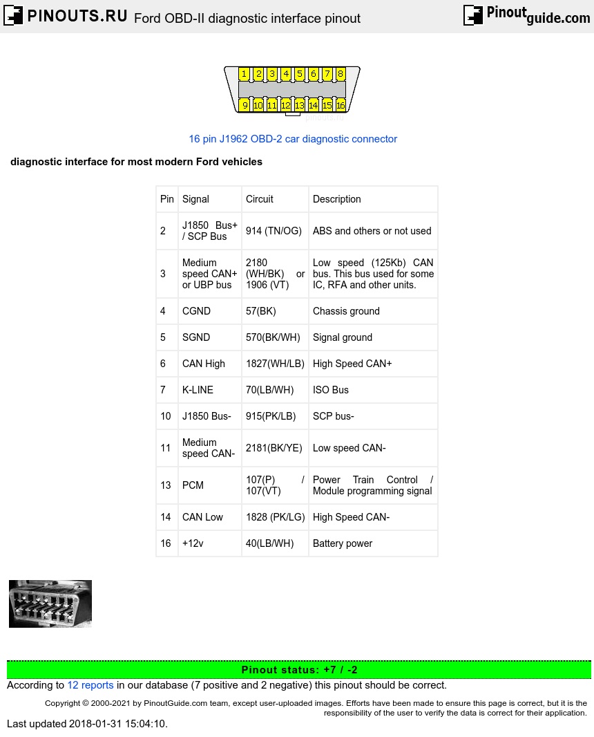
Ford OBD-II diagnostic interface pinout for Ford Ranger produced after 1995
The one you have is for 2004 or later Rangers, has CAN Bus network
2003 and earlier just use 7 wires
4 and 5 are chassis grounds
16 is 12volt power
2 and 10 are the + and - link to PCM(engine computer), - is the "signal ground" so no not the same as a chassis ground but can be, lol
Anytime you have data connection, or even a sensor connection, you have to have a "known reference ground" for the + part to mean anything, it might be exactly the same as chassis ground, but if there was an issue with vehicle ground then it might not be, so computer has a "Reference ground"
Pin 13 is a "heads up" that an OBD2 reader is plugged in, it "tells" the computer there may be "requests" made for data
Pin 7 is a Module data "request" wire, need a special OBD2 reader in most cases to get data from other modules
Pin numbers start at the wider part of OBD2 connector, and some are mounted with wider part at the bottom, so look first, lol
As shown, 1-8 then 9-16
Thank You again Ron. More great information. As I've said before I'm looking for a donor 97 Ranger 4x4 auto XLT. I need the dash harness can't find one. How about this I buy a matching GEM? Then I can use a dash harness from a 95-97 4x4 for any of my needs.
1996 or 1997, 1995 was an oddball year for Ranger dash wiring, sorry missed that earlier
But over all you don't really need to swap out the 1987 dash, it can be used with 1997 computer
Only connections between dash and 1997 computer was the CEL(check engine light), and OD OFF light
Well, here I and trying to wrap my head around electrical modules. As I’ve written in previous threads, I need this module called the GEM that controls a lot of different functions. In my project the only function I need is the 4x4 communication with the transmission. This is where my confusion comes in. There are only a couple of transmissions for my 97 Ranger 4x4 running gear These GEM’s operate the 4x4 system the same way no matter what part number GEM you have I would think. Other than maybe O.D. So here are a couple of GEM part numbers I found for sale. Why wouldn’t either be OK for my 4x4 system?
F87B-14B205-EA or F67B-14B205-DD and there are more numbers.
(What is a Generic Electronic Module? The Generic Electronic Module (GEM) is found on Ford vehicles and is basically a Body Control Computer. It controls many of the following functions on most Ford vehicles: * Warning chimes and warning lamps * One-touch down driver's side window * Daytime Running Lamps * Heated rear window * Windshield washers and wipers * Battery saver * Remote keyless entry * Illuminated entry with remote keyless entry * Interior lighting * Perimeter anti-theft * Four-wheel drive The GEM is bolted to the back of the fuse box.
Sometimes though the fuse box gets water in it and causes the same problems too.)
Yes, 1995 to 2000 the GEM was the 4x4 controller
The 4x4 part doesn't talk to transmission just transfer case shift motor
Transmission or engine computer wiring are the same for 2WD or 4x4
Yes, you can use a 4x4 GEM but its alot of wiring, not sure what its state would be if just used for 4x4 control???
You also need the Dual Relay box that was behind the GEM on the 1995 to 2000 Ranger 4x4s, thats the shift motor power relay
But you could also used 1983 to 1994 4x4 control module and its dash switch in the 1987
2001-2011 4x4s also have a separate module for 4x4 system, used the same dash switch as 1995 and up, but an all in one unit called the 4x4CM, but they were a known issue, they did fail
Ron, thank you again. In your last reply you mentioned using the 87 Bronco2 CM. Curious how that would work? You talked about GEM 4x4 relays. I cannot find anything on these relays. Nothing in any of my wiring diagrams. Thx
Ranger/B2 used a stand alone 4x4 controller, 1983 thru 1994, 3 parts plus wiring harness
Switch
Controller, has the 2 relays inside
Shift motor
1995 thru 2000 used GEM, 4 parts plus wiring harness
Switch
GEM
4x4 Relays
Shift motor
4x4 dual relay's part number is F57B-6912-AA or F57B-6912-BA
Ford called it "electric shift control module", 10 wire connector but only 7wires
Although not really a "control", lol, just 2 relays in a box, GEM activates these relays so its "the controller"
Smaller box with 2 relays inside, located behind the GEM on the firewall, so behind the radio