When you click on links to various merchants on this site and make a purchase, this can result in this site earning a commission. Affiliate programs and affiliations include, but are not limited to, the eBay Partner Network.
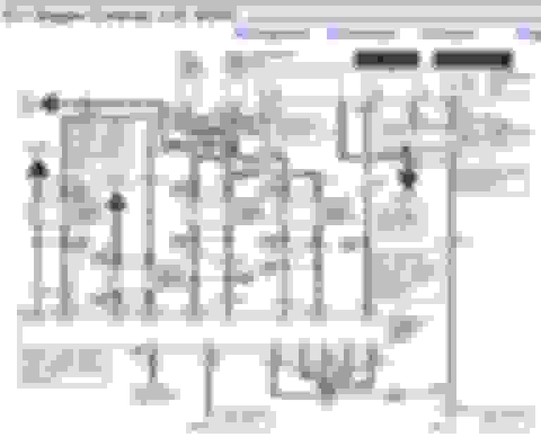
Not sure what the 2 wire plug in is but I know I took a different plug off of it... the connector with chewed wires was just floating under the intake manifold. Here�s the diagram I�m using indicating it�s going to an o2 sensor... at least I think that�s what it says, I�m proficient in reading wiring schematics...
Yes, you can see on the diagram all the O2s have a 4 wire connector, same connector number above and below each O2
In the case of the red/white is C169F(female) for the truck side, C169M is the O2 sensor 4 wire connector
I see, so it�s likely these wires lead somewhere else before the ecu... like the gem or instrument cluster...? I�ll give my uncle a ring and see if he knows what this plug goes to and why it wasn�t hooked up. Thanks!
Ok so even if the two wires were touching, it wouldn�t matter because I don�t have any of that hooked up in the first place... I�m stumped. I don�t see any other chew marks in the harness, nothing else that would cause a short or cause the Transmission issues I�m having...
Not sure why you would have suddenly gotten the P0500, never asked if it was there before the suspension work
it only shows up after warm up because thats when computer will set codes usually, closed loop
It could just be you have a non-related transmission issue that showed up a week after your suspension work, odd but certainly can happen
I am little confused to, just pull up the 1997 and 2000 5R55E diagrams to compare and BOTH show OSS sensor
Does it have a transfer case, because that is were the OSS for speedometer would be, different than 2WD because of 4Low, different than the OSS used for shifting
It wasn�t there *to my knowledge* when i left my uncles shop to drive it home it had a charging problem, so we hooked up his fancy scan tool. Turned out to be the alt trigger wire but during the scan, the only other codes were from disconnected evap ****... the transmission is 2wd, no transfer case. And to elaborate on the p0500, not only does it throw the code but from a cold start it will shift fantastically until It heats up. Then starts tripping and p0500 simultaneously...
as for a non wiring related issue, I�ve been there, done that. 2 trans shops said �shift solenoids aren�t functioning properly, replace them� so I put in a new valve body with new shift solenoids, gaskets, filter, etc. rookie mistake, this setup has roughly 5k miles on, it�s very unlikely something happened to them while sitting over the course of a year... THEN I got my hands on a scanner and saw p0500. Messed with it for a while, gave up and took the truck to a trans shop for a GOOD scan. Told me the trans functions perfectly and to come back when I fix these issues:
since then I�ve added a BOO, vss signal, disregarded the o/d button and ect code...
Thanks! Where do u get those schematics? WAY easier for a simpleton like me to understand vs the ones I have... It would probably be a good idea for me to check my grounds and tcs next, before I drive it off a cliff and collect my $500 of insurance money :)
Those diagrams were from an on-line site that I no longer have access to, the new on-line site, public library site, has the other type of diagrams, like you posted, but free so I can work with it, lol
Oh I see, any chance you have an accurate pinout diagram for the 40-something engine to chassis plug..? I suspect there might be some funny business in the tcs circuit... specifically where your diagram shows it has power input from the fuse box to a pp/o wire...
Thanks for the reply. The dash is 1994, the speedo does not work because I have a 9� axle and the old vss cable/sensor removed... do you know if it�s possible to flash a 1997 ecu to get its speed signal for the transmission from the oss? I don�t have any desire to make the speedo work, just need transmission function back...
the speed sensor on a 55r55e transmission is actually internally mounted and has a connection inside transmission. That�s why you can�t find it. You�ll have to rebuild trans to fix
 09-25-2019